Clogging mitigation through MBR membrane module design

Dennis Livingston P.E.1, Mark Parli2, Dominik Schreier3 and Matthew Rutherford4
1Technical Director, MMBR Systems, LLC | 2Technical Services Director, MMBR Systems, LLC. | 3MBR Engineering Manager, MICRODYN-NADIR GmbH | 4Technical Service Engineer, MICRODYN-NADIR GmbH
1. Introduction
Over the past two decades there have been some key developments in the design of the immersed flat MBR membrane element, including the commercialization of the composite membrane. This membrane can be termed as 'flat sheet' (FS), since the membrane elements comprise fused, flexible laminate sheets of approximately 2 mm thickness. This is to be distinct from the original 'flat plate' (FP) configuration which uses a molded, rigid support plate onto which the membrane sheets are attached around its edges.
While the energy and space efficiency of the technologies used have improved 5−8 times since the first system in 2001, protection against clogging had remained largely unaddressed until 2019 with the release of the MICRODYN-NADIR BIO-CEL®L-2 module. The L-2 module has been specifically designed to be more resistant to clogging and to allow for quicker recovery in the event of clogging. This article examines the impact of three specific design elements on the effects of clogging and the time to remediate clogging, should it occur.
There has been a significant volume of published research into membrane fouling, but very little research into membrane clogging – the accumulation of solids in-between or around the membranes. Clogging can also be referred to as 'localized dewatering' or 'sludging' if it relates to accumulation of solids specifically in the membrane channels. The agglomeration of fibrous material into rags, which collect around the membrane tank infrastructure, is termed 'ragging' or 'braiding'.
Some clogging occurs in most MBR systems regardless of membrane module type or geometry. Prevention or control measures are typically considered at the system design level and during operation. Examples include fine screening of raw wastewater and rescreening of mixed liquor. But even with adequate pre-treatment, clogging can still occur and require remediation protocols and/or specialist equipment.
2. Understanding the problem
Causes of clogging are not well understood, though possible contributors include high levels of debris or 'coarse suspended solids (CSS)', inadequate air scouring, and/or elevated mixed liquor concentrations. Some evidence suggests that sludge rheology or dewaterability may increase the likelihood of clogging.
Practitioners have developed effective ways to protect against clogging but none are guaranteed to work. A few common methods that can reduce the chance of clogging include:
- the use of 2 mm or finer perforated plate fine screening (>90% capture ratio)
- rescreening 10−15% of mixed liquor volume daily to remove reformed rags, and
- the use of non-clogging air scouring diffusers.
In general, systems that operate within manufacturer recommended guidelines can avoid or minimize clogging. However, all submerged MBR systems are susceptible and most plants are impacted at some point (Fig. 1).

Depending on its severity, clogging can significantly reduce wastewater treatment capacity, increase CIP frequency, and significantly damage membrane equipment. The time and effort required to remediate clogging for older FP technologies can vary between 5 and 12 person-weeks per million gallons per day (MGD) of treatment capacity, or 6.5−16 days per megaliter per day (MLD). The cost and risk associated with clogging can thus be substantial.
A survey of 221 FP MBR installations serviced from 2001 to 2013 revealed clogging to have knowingly impacted system performance on one or more occasions at 91 plants. The process upset at 126 of the plants was identified as 'unknown'. Similarly, in a survey of 60 FS installations serviced between 2012 and 2019, 25 had confirmed clogging events while the upset at 30 plants was characterized as 'unknown'.
Although clogging can impact any type of membrane technology, little is known about the lasting effect of one or more events. Some research suggests long-term permeability decline in ultrafiltration HF systems, and occasional mechanical damage of FS/FP modules if clogging is left unchecked (Fig. 2). Regardless of the element type, damage caused by clogging often occurs at the top of the plate or sheet.

3. Manual clogging/sludging removal (manual/physical cleaning of elements)
In the event of sludging, agglomerated solids can be removed in part through vigorous air scouring in situ combined with recovery cleaning. However, for significant sludging, the material must be physically removed by water jetting or by being scraped off by hand. For HF technologies, materials must be manually pulled from fibers. For FP technologies, the membrane channels can sometimes be cleared by water jetting, but more severe sludging demands individual plates to be removed from cassettes/modules and cleaned by hand.
Based on site experience of FP membrane sludging on multiple occasions over a period of 19 years, the average time for its remediation on a plate-by-plate basis varies between 0.33 and 0.59 m2/min. The de-sludging time depends on parameters such as packing density, sludge composition, site conditions, and technician or operator experience.
Agglomerated solids can be removed from FP and FS cassettes using a spray nozzle (Fig. 3a−b), with the membranes in situ (i.e. without disassembly of the cassettes). For older FP equipment, individual plates are often removed from cassettes for cleaning (Fig. 3c) and the solids scraped or sprayed from each element. For enclosed FS modules, the casing can be removed, and sheets sprayed from the sides. In all instances, some in situ cleaning sequence generally precedes hand washing and follows mechanical cleaning for FP, FS, and HF type modules.

4. Bespoke equipment for clogging removal (physical cleaning of FP cassettes)
To eliminate the need for spraying or scraping individual flat plates, machines have been built to remove clogging at the cassette level. An early version of a cassette cleaning machine was called the Membrane Treatment System, or MTS. The MTS was roughly 14 m x 3 m x 3 m and required nearly 22,680 LPM of clean water to achieve adequate water jetting velocities and volumes. The added setup and handling times meant that the overall processing speed equated to the element cleaning method at 0.59 m2/min. The process was generally safer (i.e. required less plate handling) but not faster than previous methods. Ultimately it proved faster to clean plates manually for plants with a rated capacity of less than 8,000 m3/day.
An improved technology was later built to clean a 'block' FP module design. This machine is smaller, demands around 2,268 LPM of water, and has an overall processing time closer to 0.8 m2/min.
5. Module design for clogging mitigation
In 2017, MICRODYN-NADIR evaluated methods to reduce the potential for clogging, and to minimize its impact. The first step was to remove the side plates (Fig. 4a−b). The intention of this design change was to minimize the effects of 'air channelling' caused by clogging, to facilitate equipment inspections, and to reduce the maintenance required to remove clogging should it occur.
Clogging versus fouling in immersed membrane bioreactors
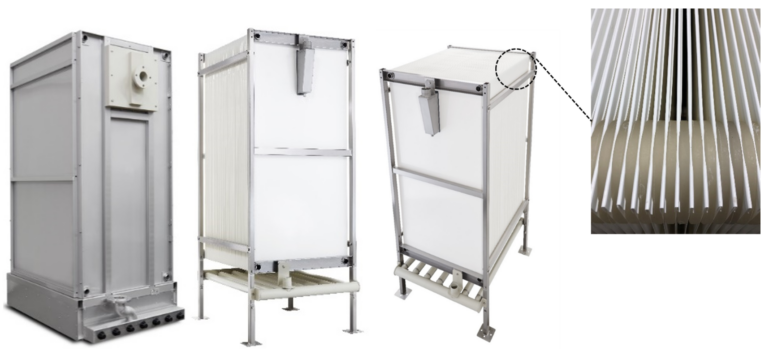
In 2018, two additional improvements (Fig. 4c) were tested specifically to address the most common types of clogging. A reinforcing bar was added to the top edge of each membrane sheet and a shock absorbing ring added between the upper support rings. Extended, full-scale pilot testing was conducted to quantify the impact on the module durability.
5.1 Pilot trials, pure water
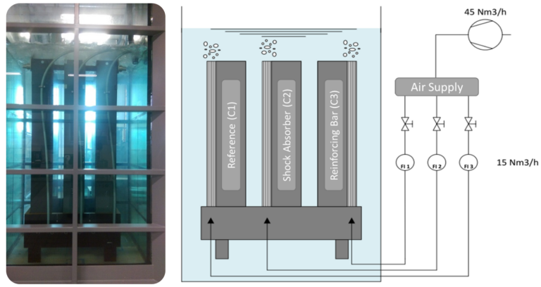
A 12-month validation study was conducted based on three cassettes (Fig. 5) continuously aerated under accelerated conditions at ~8 times the normal air-scour rate to provide conditions intended to challenge membrane integrity. A reference cassette (C1) based on the L-1 module design (Fig. 5) was used as a control. A second cassette (C2) was equipped with shock absorbers at the top rings, while a third cassette (C3) had reinforcing clip bars added. After 85 days, the C2 cassette with only shock absorbers was replaced with a fourth cassette (C4) equipped with both the shock absorber and the clip bar.
Key risk areas − modes of clogging-related mechanical failure − were identified and the time taken before the first observation of a particular damage type recorded as an indicator of durability. The two recognized precursors to membrane mechanical failure were microcrack and kink formation, occurring at the eyelets and the top edge, respectively. The unmodified, older design L-1 (cassette C1) showed the first signs of damage within 160 hours (Table 1), whereas no cracks or kinks were observed for the modified L-2 design (cassette C4) after 6,263 hours of operation.
| Top (Sheet) Edge − Microcracks | Top (Sheet) Edge − Kinks | Eyelets − Microcracks | Eyelets − Kinks | |
|---|---|---|---|---|
| C1 (Reference) | 160 hr | 160 hr | 182 hr | 414 hr |
| C4 (Absorbers + Bars) | >6,263 hr | >6,263 hr | >6,263 hr | >6,263 hr |
5.2 Site-based data
Performance of the open-sided L-2 module design was evaluated at three sites (Table 2), with the time in service for each plant ranging from 7 months to 20 months. In each case, the observed in situ ragging was characterized as 'significant' during one or more inspections. The presence of rags found on submerged diffusers, pipes, mounting hardware, and modules indicated an elevated risk of clogging for each installation. However, no significant sludging or sheet damage was observed at any of the sites.
| Plant 1 | Plant 2 | Plant 3 | |
|---|---|---|---|
| Time in service, months | 7 | 10 | 10 |
| Module type | L-2 | L-2 | L-2 |
| Number of modules | 8 | 6 | 4 |
| Observed ragging (in situ) | Significant | Significant | Significant |
| Observed sludging (between sheets) | none | none | none |
| Observed ragging (module inlet) | <10% | <10% | <10% |
| Observed sheet damage | none | none | none |
The absence of sludging at the three L-2 sites evaluated suggests that an open-sided module design is less susceptible to this operational challenge than an enclosed module. Data from a fourth facility, Plant 4, showed similar results. Plant 4 is equipped with open-sided modules that were not supplied with reinforcing bars or shock absorbing rings. At Plant 4, looking at nearly two years of data, the average mixed liquor suspended solids (MLSS) concentration was 10.9 g/L and the average CSS content was 940 mg/L (with a maximum of 1,800 mg/L). Despite the high CSS content, compared with an advised maximum of 30 mg/L for one conventional FP configuration, no sludging was observed at this site after 20 months in service.
6. Clogging removal
For older generation FS modules (with the sides on), clogging remediation can take roughly 8 hours for one module equipped with 480 m2 of membrane area, or 1.0 m2/min. For the open-sided L-2 modules, factory information suggests that cleaning can take less than 20 minutes for moderate sludging. This estimate implies a declogging rate of up to 24 m2/min – around 40 times faster than the 0.59 m2/min for some conventional FS and FP modules (Section 4).
For declogging (or rinsing) purposes, water is poured onto modules at a rate of 284–590 LPM based on a 50 mm hose and 204-408 LPM for a 75 mm hose (Fig. 8). The water jet is introduced at a height of 150–600 mm above the modules and at an angle of no more than 5° to the membrane surface.

6.1 Field data, declogging
During a recent site inspection, up to 50% sludging described as moderate to severe was observed in two out of five reactors. For remediation, sludging was removed from 14 modules within an 8-hour period using a 2.5-inch (65 mm) water hose at a flow rate of 284–378 LPM, equating to a declogging rate of 14 m2/min. Modules remained in situ during the rinse process; removal from the tank was not required.
7. Conclusions
Three specific module improvements have been implemented to minimize the effects of clogging, comprising:
- removal of the sides to minimize sludging and facilitate low pressure water rinsing
- the addition of reinforcing clip bars to the top edge of membrane elements, and
- the further addition of shock absorbing rings installed between upper support rings (or eyelets).
The removal of the side panels was to mitigate the accumulation of solids within the channels. The addition of reinforcing bars and shock absorbing rings increased mechanical robustness.
Extensive full-scale testing has indicated an increased resistance to the effects of clogging, confirmed by site inspections that have indicated a decrease in clogging severity. Finally, factory tests indicate an achievable declogging rate of 24 m2/min, and field data confirmed an in situ recovery rate of 14 m2/min without the use of lifting equipment, high pressure water, or chemicals for moderate to heavy sludging.


