MBR Components

MBR building blocks
As with a conventional biological wastewater treatment process, an MBR is a combination of tanks, pipework, pumps and blowers, with the addition of the membrane differentiating it from classical processes.
A simple design of a small MBR has been provided by Lo et al (2015). This is a general design for a municipal wastewater treatment based on an immersed membrane and an MLE (modified Ludzack−Ettinger) process. The specifications of the individual pieces of equipment (power, flow and/or pressure ratings) then depend on the application and assumptions made.
Most MBR installations must also include a control system for regulating flows and pressures.
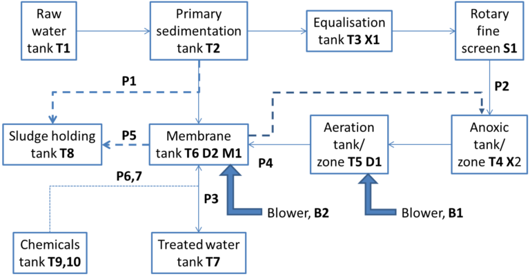
| Category | Component(s) | ID | Description/purpose |
|---|---|---|---|
| Tanks | Raw water | T1 | Storage tank for inlet wastewater |
| Primary sedimentation | T2 | Removal of gross, settleable solids | |
| Equalisation (EQ) | T3 | Equalisation of flow | |
| Anoxic (Ax) | T4 | Denitrification | |
| Aeration (Ae) | T5 | Nitrification and biological oxidation | |
| Membrane | T6 | Membrane separation | |
| Treated water | T7 | Storage of permeate water | |
| Sludge | T8 | Storage of wasted sludge | |
| Chemicals storage | T9, T10 | ||
| Pumps | Settled sludge transfer | P1 | Submerged, settled sludge to sludge storage tank |
| Feed | P2 | EQ tank through rotary screen | |
| Permeate | P3 | Self-priming, membrane suction filtration | |
| Sludge return/discharge | P4 | Submerged, sludge recirculation and excess | |
| Sludge transfer | P5 | WAS to dewatering | |
| Chemicals | P6, P7 | Cleaning chemicals transfer to membrane, x2 | |
| Blower | Process | B1 | Biological process aeration |
| Membrane | B2 | Membrane scouring | |
| Mixer | EQ tank mixer | X1 | High speed, equalisation tank |
| Ax tank mixer | X2 | Low speed, anoxic tank | |
| Screen | Rotary screen | S1 | Fine screening of feed |
| Membrane | Membrane module | M1 | FS membrane plus frame with built-in aerator |
| Diffusers | Fine bubble diffuser | D1 | Process aeration |
| Coarse bubble diffuser | D2 | Membrane aeration |
Membrane modules terminology
Terms for the individual components of a membrane technology are used inconsistently for membrane bioreactors.
- An ‘element’ can be considered to be the smallest replaceable component of the membrane technology.
- The term ‘module’ normally applies to a single element for a rectangular hollow fibre technology, but usually to a collection of elements in the case of flat sheets.
- The term ‘stack’ can be considered to apply generally to a collection of elements, with the terms ‘rack’, ‘unit’, ‘cassette’ and ‘skid’ (for an externally-mounted array of modules) also being used.
- A line of immersed stacks is usually called a ‘train’, and the train may include an aeration lane of the biological tank if one aeration lane is associated with a discrete row of immersed membrane modules.
| Component | Flat sheet (FS) | Hollow Fibre (HF) rectangular panel | Hollow Fibre (HF) cylindrical bundle; Multitube (MT) |
|---|---|---|---|
| Element | Panel, element, sheet, cartridge | Module, sub-unit | Module |
| Collection of elements I | Module, cassette, unit | Rack, cassette, cartridge, module | Skid |
| Collection of elements II | Stack, frame | Stack, frame |
Other key terms and abbreviations
A number of abbreviations are used for the different polymeric membrane materials, the first letter invariably being 'P' (for 'polymeric'). For ceramic membranes the chemical formula is used to identify the membrane material.
The configuration of the MBR process defines how the membrane is integrated into the overall MBR process. It can be either immersed (or 'submerged') in a tank (hence the term 'iMBR') or placed outside of the tank as a sidestream (i.e. 'sMBR').
The MBR process configuration is to be distinguished from the membrane configuration which defines the membrane geometry and permeate flow direction. The main three geometries used for MBR technologies (Table 1) are flat sheet or flat plate (FS), hollow fibre (HF) and multitube (MT).


