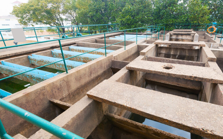
Process and membrane aeration

Aeration is needed both for the process and the membrane tanks for an immersed membrane bioreactor (iMBR), and normally only for the process tank in sMBRs. Aeration accounts for the major part of the energy consumed by an iMBR installation.
Process aeration
The aeration demanded for biological treatment, often referred to as the ‘process aeration’, is governed by the inlet and outlet levels of biodegradable organic carbon and Kjeldahl nitrogen levels, Kjeldahl nitrogen (KN) essentially being the biologically oxidisable nitrogen. The absolute difference between inlet and outlet levels of Kjeldahl nitrogen (denoted Total Kjeldahl Nitrogen or TKN) and biodegradable organic carbon (which relates to the Biochemical Oxygen Demand or BOD) defines the load. The load in turn determines the oxygen required to convert organic carbon to carbon dioxide and KN to nitrate (by 'nitrification').
The oxygen rate needed to carrry out the biochemical transformations in turn determines the aeration rate, given that air contains around 21% oxygen. The aeration rate is also determined by the proportion of the oxygen in air that is used by the microbiology for the biochemical reactions, referred to as the oxygen transfer efficiency (OTE). The OTE is influenced by a number of factors, including the type of aerator, the aerator depth in the tank, the mixed liquor suspended solids concentration and the temperature.
It is common to modify the aerobic treatment to allow the biochemical reduction of nitrate, formed by nitrification of KN, to nitrogen gas (N2). This is achieved by recirculating sludge from the membrane tank to a zone upstream of the aeration tank. Under the anoxic (i.e. reduced dissolved oxygen levels) conditions prevailing in this region, specific bacteria (‘facultative anaerobes’) develop which are able to use the organic carbon to reduce nitrate to nitrogen gas.
Denitrification by this method, the ‘Modified Ludzack-Ettinger’ process, provides a simple and effective method of nutrient removal, provided there is sufficient organic carbon present in the influent. It both removes nitrate and slightly reduces the oxygen demand for the downstream aerobic process.
Membrane aeration
Membrane aeration – or ‘scouring’ air – is normally achieved via coarse bubble aerators positioned beneath the membrane units of an iMBR. Aeration is also used in air-lift sidestream MBRs (A-LsMBRs). In both cases the aeration demanded can be normalised to produce the specific aeration demand (SAD). Normalisation can be either against the membrane area (SADm, taking units of Nm3/(m2.h)) or against the permeate volume (SADp, Nm3/m3).
SADp is then directly proportional to the specific energy demanded for membrane air scouring, or SEDAm, since all other components of air pumping (namely the blower efficiency, aerator depth, inlet air pressure, aerator type, and ratio of air and water enthalpies) are constant for a specific installation. SADp is the ratio of SADm to the flux in consistent units, i.e. in m/h. Energy efficiency is improved both by increasing the sustainable flux and decreasing the membrane air scour rate required to sustain this flux.
Given the impact of aeration on the energy consumption of the MBR process, a key aspect of MBR technology design is the design of the aerators. Aerators used for the process tanks are designed to promote oxygen mass transfer into the mixed liquor. Fine bubble diffusers (FBDs) are generally used for this duty, normally configured as either disc or tubes. Enhanced oxygen transfer can be achieved using high-shear aerators, but these also have the effect of breaking up the flocs which results in the release of foulant material.
Membrane aeration, on the other hand, employs coarse bubble aerators. These can have various designs, but all are based on the principle of maximising the shear possible from passing large air bubbles across the membrane surfaces. Improvements in membrane aerator design and operation since iMBRs were first commercialised have seen significant decreases in the SADp, and thus energy demand, of iMBRs over the years.
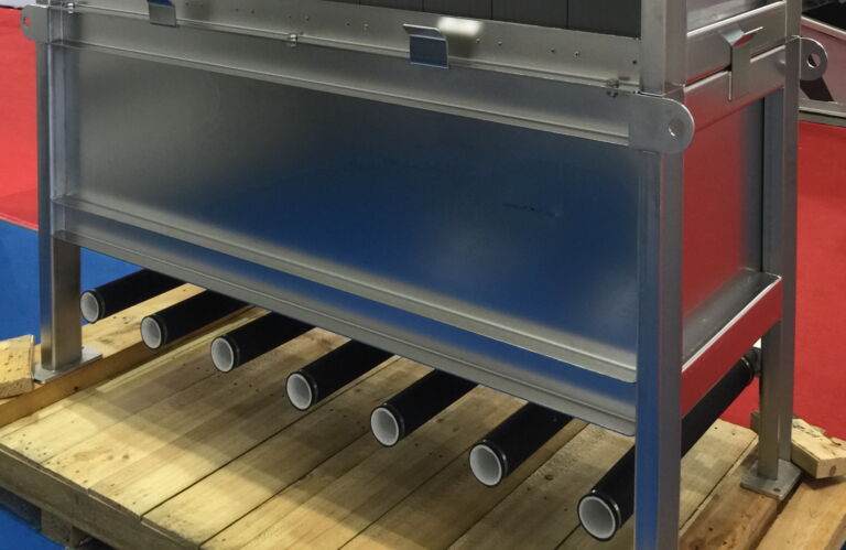
Blowers
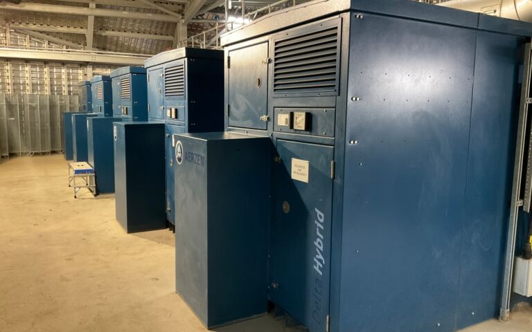
For both the membrane and process operations, aeration is provided by blowers. The blowers are usually of different ratings for the two different applications in large municipal MBR plants. For such large installations, an individual blower is often assigned to each aeration lane and each bank, or possibly pairs of banks, of membrane modules.
