MBR Screening Part 2: Selecting an MBR screen

James Impero and Kevin Hammler
In Part 2 of this two-part article, James Impero, Senior Engineering Specialist, Municipal Global, and Kevin Hammler, Field Service Technician, Ovivo USA, LLC summarise the operational factors to consider when selecting an MBR screen
In MBR Screening Part 1, we provided a full overview of MBR screens and their performance. We now consider some of the key facets to take into account when selecting a screen for your MBR design. These key facets include the screenings capture ratio, screen apertures, screening flow velocity, ancillary processes and coarse suspended solids, and screen maintenance.
1. Screenings capture ratio
The screenings capture ratio (SCR) represents the amount of solids removed by the screen as a proportion of the total coarse solids load, and as such is analogous to membrane rejection. Its value is dependent on both the rating and rotation speed of the screen, as well as on the velocity of the wastewater travelling through it. Increasing the speed of screen rotation tends to decrease the screenings capture, since it also reduces the retention time in front of the spray nozzle coverage and overlapping spray pattern. This reduces the cleaning efficiency, causing dirty panels to be reinstated into the dirty wastewater. This in turn exacerbates the incomplete screenings removal causing higher headlosses and higher velocities through clean holes.
A rotational speed that is too low causes instantaneous capture through matting of debris, but also causes the mat to sustain a shorter spray water cycle retention time leaving some of the debris stuck to the screen panels, again putting dirty panels back into dirty water flow. This can also increase blinding and headloss which will then tend to allow solids to be forced through the screen apertures. Slotted escalator and step screens are particularly susceptible to this issue, with the accumulating solids forming thick mats from which extraneous solids are forced through the screen and into the screened water. These technologies are thus less favoured for MBR applications, or others where fine/ultrafine screens are employed downstream.
| Screen panel aperture, mm | Screen rotation, mm/s − 50 | Screen rotation, mm/s − 75 | Screen rotation, mm/s − 150 |
|---|---|---|---|
| 6.0 | 81% | 78% | 75% |
| 5.0 | 83% | 80% | 77% |
| 3.0 | 95% | 93% | 90% |
| 2.0 | 97% | 95% | 92% |
| 1.0 | 98% | 97% | 97% |
| 0.5 | 99.7% | 99.7% | 99.7% |
2. Screen apertures
Round-hole panels provide true aperture screening, whereas the true rating of a slot or bar screen depends on the length of the rectangular aperture and not just the width. Engineering manuals stipulate that a slotted panel must be 2−2.5 times smaller in rating to approach or equal a round-hole aperture in true screening capability. Slots or bars, while less selective, offer reduced headlosses and so can pass greater flows in restricted-width channels or lower-depth inlet waters.
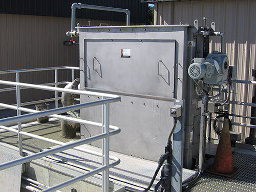
Wire or polymesh screens are much closer in open area parity to a round-hole aperture. Wire or polymesh square apertures of equal area size to round holes will offer an additional open area advantage when based on ultrafine apertures of 1 mm and 0.5 mm or less due to the thinness of the wires: a greater surface porosity is attainable than for a screen based on circular holes. This provides great advantages when sizing a screen with these ultrafine apertures. For wire or polymesh screens, the material’s innately higher open area allows a significant reduction in velocities while maintaining the size of the screen and its associated fabrication cost. The disadvantage of wire or polymesh is that an absolute maximum of 1.3 ft/s, and preferably 1 ft/s, must be adhered to. Compressing the screenings against wire or polymesh screen panels at excessive flows makes it difficult to remove the debris using low-pressure wash water from spray manifold systems. This then causes partially cleaned screen panels to rotate back into the wastewater flow, exacerbating the problem.
A properly-sized 2 mm screen will remove 94−96% of all pseudo-spherical particulate screenings, whereas a 1-mm screen will remove up to 98.7% of all filamentous particulate screenings such as human hair, cotton and wood fibre. Filamentous debris can pass readily through a 3-mm and 2-mm fine-screen aperture, as well as 2-mm and 1-mm slotted screens, if they approach the screen orthogonally (i.e. end first). It is known that these solids may then recombine to form rags or braids within the process and membrane tanks (Stefanski et al, 2010). This recombination/agglomeration of fine solids can then clog pumps, mixers, air nozzles and distribution systems and the interstices between the membranes. This then demands further maintenance and increased cleaning schedules that take up operator time, and the increased workload often leads to reduced or incomplete maintenance which inevitably leads to membrane damage and expensive replacement cost. Decreasing the screen aperture to 1 mm or less reduces breakthrough of filaments, and a 0.5-mm aperture almost eliminates breakthrough completely (99.7% screenings capture) and causes complete matting of the screen surface which may not be successfully cleaned using 30−60 psi wash water unless proper retention time is attained by the rotational speed of the screen.
3. Screening flow velocity
Screen performance is defined by the flow, screen rotation and the screenings capture ratio. Sustaining operation demands that the flow velocity through the screen is appropriate to the screen rating − analogous to the flux through a membrane. Excessive flows reduce the efficacy of the wash cycle in removing the retained solids. Thus a screen rating of 2−3 mm demands a maximum flow of 0.45 m/s (around 1 million GFD!), whereas for a 1-mm rating this must be reduced to below 0.37 m/s. Also, as with a membrane, the fine screens themselves require protection with a coarse screen upstream: a screen rated at 1 mm or less demands that the coarse screen upstream removes up to 81% of the coarse solids and not less than 65%.
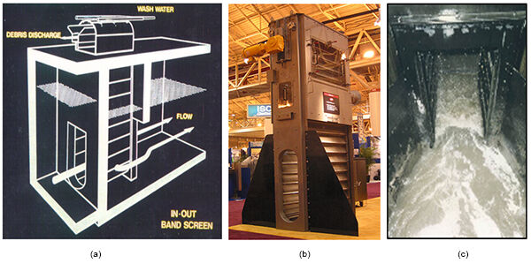
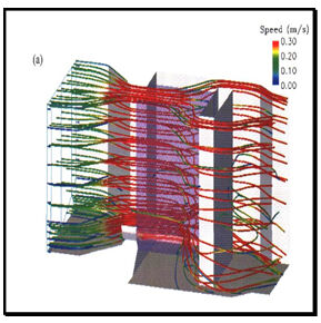
For 6-mm round-hole headworks screening (coarse screening), a maximum velocity of 2.5 ft/s (0.76 m/s) at peak flows at the screen panel applies. Peak capture ratios arise at 2.0−2.5 ft/s (0.61−0.76 m/s). Controlling velocity at the headworks screen is exceedingly important since a high capture ratio at the coarse screen reduces loading on the downstream fine and ultrafine screens. These coarse screens should be sized based on operation at or below 50% capacity. Headloss curves rise asymptotically beyond the 50% threshold, causing the velocity of the open screen panel holes to increase commensurately and pushing solids through the apertures. This is the primary issue observed in the field when fine screens and ultrafine screens are overloaded. Fine screens operating 80%−85% instead of 35%−40% of the time diurnally causes premature deterioration of the screens, as well the increased velocity which forces debris through the screen apertures.
6-mm slotted or bar screens at the headworks should not be operated above 2.0 ft/s (0.61 m/s), due to the issue of solids being forced through the slots at excessive flows. This can then cause excessive loading and blinding of downstream membrane protection screens. It is suggested that coarse screens should capture a minimum 65% of all screenings to reduce the loading on the downstream membrane screens. On this basis, aperture slots or bar spacing of 3/8 inch (9.5 mm), ½ inch (12 mm) or ¾ inch (19 mm) are not recommended since they are unlikely to be capable of 65% capture. Next to high screen velocities, this is the second most common cause of fine and ultrafine screen overloading and subsequent failure to protect membrane basins and systems from undesirable debris.
Finer screens similarly demand more conservative velocities. For 3-mm and 2-mm round-hole apertures (fine screening), the maximum recommended velocity is 1.5 ft/s (0.46 m/s), with 1.3 ft/s (0.4 m/s) at average flows. Similarly, for 1-mm mesh panels − square holes for ultrafine screening − corresponding values are 1.2 ft/s (0.37 m/s) and 1.0 ft/s (0.31 m/s), and for 0.5-mm mesh panels, 1.0 ft/s (0.31 m/s) and 0.8 ft/s (0.24 m/s).
| Screen aperture | Velocity 3.0 ft/s (0.91 m/s) | Velocity 2.0 ft/s (0.61 m/s) | Velocity 1.0 ft/s (0.31 m/s) |
|---|---|---|---|
Note: | |||
| 3.0 mm Plastic panel (round hole) | 52% screenings capture (SCR) | 67% screenings capture (SCR) | 93% screenings capture (SCR) |
| 2.0 mm Plastic panel (round hole) | 59% screenings capture (SCR) | 70% screenings capture (SCR) | 95% screenings capture (SCR) |
| 1.0 mm (poly-Square mesh) | 76% screenings capture (SCR) | 82% screenings capture (SCR) | 99% screenings capture (SCR) |
4. Simplified test procedure for screens
4.1 Suggested Sieve Test Procedure for testing whether a screen is properly sized and removing sewage debris larger than the screen panel’s aperture
The following sieve test can be used to determine the amount of material that is contained in the mixed liquor of an activated sludge wastewater treatment plant. It can be used to quantify the effectiveness of the pretreatment and screening equipment of the plant. A poor sieve test result indicates that there may be a problem with the pretreatment systems, while a good result indicates that the pretreatment is likely working well.
The sieve test requires a relatively large sample volume of mixed liquor (typically 60−200 L). For this reason, it is important that the sample location be convenient for operator access and from a safety point of view. The best sample location is typically a sample valve located on the discharge side of the mixed liquor recirculation pump.
Materials required:
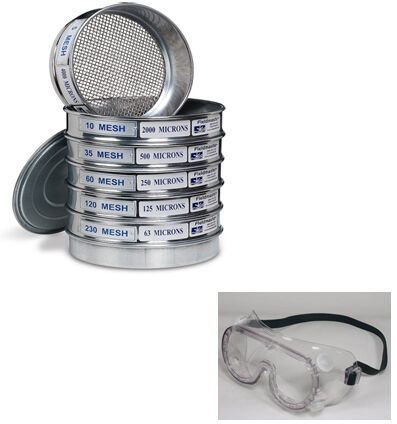
- Pail or bucket to collect the mixed liquor from the sample port
- Plastic gloves
- Eye protection/face shield
- Stack of sieves
- Clean wash water (garden hose with spray nozzle)
- Analytical balance (scale)
- Aluminum or stainless steel trays (sieves)
- Oven (105°C).
Procedure:
1. Assemble a stack of sieves of the following sizes (largest sieve on top): 3.0 mm / 2.0 mm / 1.0 mm.
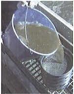
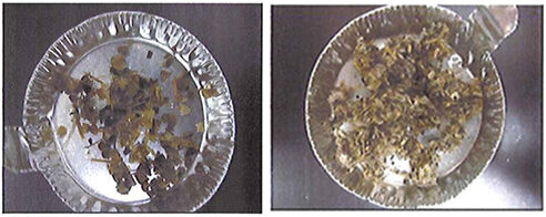
2. Collect from a sample port and carefully pour a known volume (60–200 L) of representative mixed liquor through the sieves (see picture below). The correct volume of mixed liquor to use for the test will depend on how much material is collected on the sieves. The key is to use a sample volume that is large enough to ensure that enough material is collected to be easily weighted (i.e., you should collect at least as much material in this procedure as shown in the pictures of the trays in Figure 4). For a very clean or very thin (low MLSS) sample, this may mean a sample volume of 200 L or more. For a very dirty or very thick (high MLSS) sample, this may mean a sample volume of 60 L or less.
3. Pour clean water through the sieve periodically (if necessary), taking care not to lose any screenings by spraying them out of the sieves.
4. Shake the sieves gently and wash through with clean water to rinse away the biomass and to clean the collected screenings.
5. Record the weight of each of the empty trays (in grams).
6. Separately collect the screenings from each sieve, and transfer to pre-weighted aluminum or stainless steel trays.
7. Dry the trays of screenings in an oven at 105°C for a minimum of 8 hours, or overnight.
8. If the mixed liquor suspended solids (MLSS) of the sample is not known, then a separate sample of the same mixed liquor should be collected and analysed for MLSS.
9. Weight the trays again to determine the dry weight of the screenings. Record the weight of each tray in grams.
10. For each sieve size, calculate the screenings concentration using the following equation:
11. For each sieve size, normalise the results calculated in Step 10 for MLSS concentration using the following equation:
Disposal:
The waste material used in the sieve test procedure can be disposed of in the regular trash or in the same container that is used to collect the screenings from the raw wastewater.
5. Consequences of downstream coarse and fine suspended solids
Properly designed screening can mitigate problems such as membrane fouling and membrane damage due to sharp debris. Every 1 mg/L of hair, fibre, or other debris equals 8.35 lbs of recombined, agglomerated and/or matted debris per MGD wastewater.
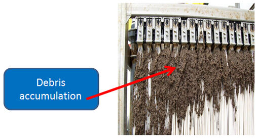
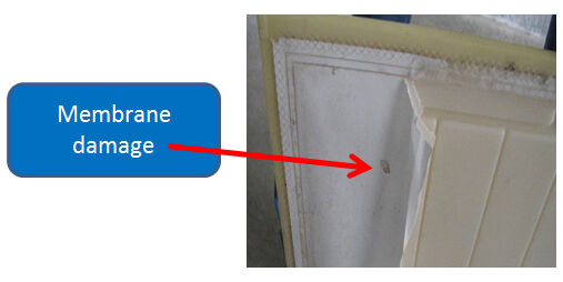
Figure 7 shows examples of damaging and high-maintenance debris removed at entrances and from membrane basins post coarse and fine screening:

6. Ancillary processes and coarse suspended solids
Other unit operations employed at the headworks comprise grit removal and comminution (or grinding). Grit removal normally follows coarse screening and is required to protect downstream processes such as silting of aeration systems in the membrane basin and abrasion of membrane surfaces during coarse air diffusion, as well as damage to the fine screens. Screens generally have too many moving parts to be used for grit removal: grit can damage seals and penetrate the moving parts, causing premature wear and demanding more frequent maintenance and parts replacement. Grinders reduce the capture ratio of the screens. It has previously been assumed that reducing the size of the solids commensurately reduces their impact with respect to clogging. However, it is now recognised that the formation of the characteristic rags arises from the re-combination of solids which can be below the screen rating size but then agglomerate in the membrane and process tanks to form rags which may be several feet in length (Stefanski et al, 2011, see feature ‘From Rags to Hitches’).
An indication of the extent of re-combination, and therefore membrane channel clogging propensity, can be surmised from the coarse suspended solids (CSS) concentration measurement, the CSS being the concentration of dry solids retained by a 150 µm-rated sieve. Although grinding may protect the pumps, it generates other problems which are costly to overcome.
The target CSS is dependent on the type and channel dimensions of the membrane: MBR membrane modules designed with greater inter-membrane separation (or interstices) can tolerate higher CSS levels than those with smaller ones. Thus, for example, the Ovivo OV membrane module (based on the MICRODYN-NADIR GmbH BIO-CEL®) has a recommended maximum CSS level of 1,000 mg/L, whereas for the SP module (the Kubota ‘block’) the same guideline value is 30 mg/L. The standard 510/515 Kubota panel is assigned a value of 200 mg/L. Because of the re-combination issue, it is sometimes recommended to screen the return activated sludge (RAS) from the membrane tank to suppress CSS formation, though properly-sized and operated pre-screening is still required.
7. Primary causes of screen failure and proper screen maintenance procedures

Screen failures arise when they are either mis-sized or poorly maintained, allowing coarse solids to bypass screens or cause excessive differential headloss to occur. Failure types include:
a) broken teeth on the bars and the raking mechanism, caused by stones, concrete chunks from degrading civil works and intake pipes, as well as hard man-made objects that jam into the bars and break front and back raking systems or foot sprockets;
b) panel blinding and headloss from either gross solids, high viscosity feeds (possibly associated with lower temperatures and higher viscosities through RAS and WAS return lines) or excessive flows, which then impair the spray wash cleaning;
c) seal failures, caused by grit, rags, plastic bags or objects jamming and separating the seals from the screen frame causing bypass of debris into the moving parts of downstream unit operations, as well as macerated plastics and debris damaging the neoprene rubber seals;
d) the lack of sequential screening, i.e. fine screening without upstream protection by a coarse screen, is often the primary reason why solids bypass the fine screen. Coarse solids (debris) can cause rapid blinding of the fine screen, demanding manual intervention. Poor maintenance of brushes on stainless steel perforated plate screen panels is the most common cause of hair, cotton and paper fibre bypassing screen panels through round holes.
8. What’s new in screening to look forward to?

Dual-aperture screening (Figure 9) is a new screening technology which was primarily developed for small flow rates where multiple screens and grit systems can be prohibitively expensive to install for the protection of membrane facilities. A dual-aperture screen, combined with an ancillary grit reduction system, is provided in standard design for the cost-efficient screening and grit reduction up-front of flat plate and hollow fibre membrane systems. It provides first-stage coarse screenings, followed by grit reduction, followed by fine screening, while incorporating an integral collection, dewatering screenings and disposal system. The ‘duet drum screen’ was designed for pumped flow, in-tank and gravity flow, in-channel sewage applications and protection of downstream membrane systems.
9. Summary
Screening represents perhaps the most pivotal component of a membrane bioreactor-based treatment scheme for municipal wastewater treatment. Appropriate selection and sizing, along with proper maintenance, of the screen is therefore of critical importance in sustaining operation of the plant. This includes selection and O&M of the primary coarse screen and grit removal technology, since this reduces the load on the fine screen and thus protects both the fine screen and the downstream membrane. As with the membrane itself, the velocity through the screen − analogous to the flux through the membrane − is the key design parameter and, as with the membrane, there is little financial justification for under-specifying the screen on this basis, given the potential impact on operational costs.


