MBR Screening Part 1: MBR screen designs and performance – an overview

James Impero and Kevin Hammler
In Part 1 of this two-part article, James Impero, Senior Engineering Specialist, Municipal Global, and Kevin Hammler, Field Service Technician, Ovivo USA, LLC summarise the different designs of MBR screens in use today
1. Why is screening important?
The importance of screening upstream of a membrane bioreactor has been widely acknowledged since the early pilot trials by DHV in the Netherlands (van der Roest et al, 2002) and remains a key concern for MBR practitioners today (see our 2015 MBR Survey results). Screening protects the membrane from mechanical damage from sharp or abrasive particles and from clogging from hair and matted cotton fibre. While any screen is better than no screen at all, it is critically important to have a properly designed and sized screening system to limit the screen cleaning frequency, maintain screen operation and capture efficiency, as well as to extend membrane warranties.
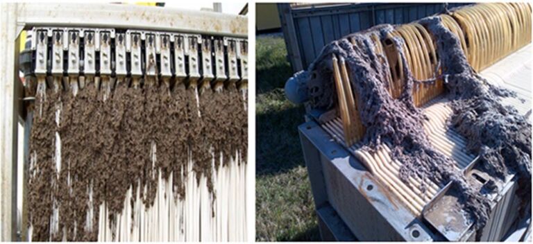
The build-up of solids within components of the membrane tanks is a very familiar challenge in MBR operation. This can be manifested either as the accumulation of solids between membrane sheets or fibres, or as characteristic ‘rags’ or braids (Figure 1). In either case, the amount of solids involved as a proportion of the flow can be very small. For example, for a flow of 5 MLD (5 megalitres/day or 5,000 m3/d), the deposition of just 1 mg/L of solids will produce an accumulation of 5 kg solids daily, or approaching two tonnes annually. Clearly, not all the incoming inert solids will deposit onto the membrane components or aeration scouring manifolds, but it is also obvious that the risk of this happening can be reduced by limiting the load exerted by such material.
2. Screen ratings and designs
Just as the crucial nature of screening is now widely understood, so also are the key differences in screen ratings and designs. In general, ratings applied for the different functions within a wastewater treatment works can be summarised as follows (Figure 2):

| Coarse screening | 15 mm, preferably 6 mm | headworks screening and degritting |
| Fine screening | 3 mm, preferably 2 mm | flat sheet/panel MBRs |
| Ultra-fine screening | 2 mm, preferably ≤1 mm | hollow fibre MBRs |
Screens come in a number of different designs, each suitable for a particular purpose. In summary, the most common screen designs are as follows:
- Spiral-screw gravity-flow stationary screens
- Through-flow, escalator, step screens
- Pumped-flow rotational drum screens
- Gravity-flow rotational drum screens
- Centre-flow and dual-flow band screens
- Single-entry, double-entry and duet drum screens.
2.1 Spiral-screw screens
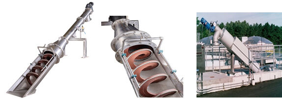
The spiral-screw screen (Figure 3) can be used for 6-mm coarse screening protection, commonly up to 8 MGD capacity, and 3-mm or 2-mm fine screening applications up to 3.5 MGD (150 L/s). This screen is more properly employed upstream of fine or ultra-fine screens and grit removal (headworks screening), but is also often used for membrane protection.
This screen design uses a static stainless steel perforated-plate screen panel that is cleaned by brushes along the circumference of the rotating screw. The brushes remove clogged debris in the perforated holes but, due to the sharp edges of the punched holes in the stainless steel plate, the brushes cause hair and cotton fibre to be severed as they scrape the debris away from the holes towards the washing compactor at the top of the screen. Around 15−25% of the filaments of hair and fibrous cotton debris is subsequently washed downstream on the clean water side of the channel.
2.2 Through-flow, escalator, step screens
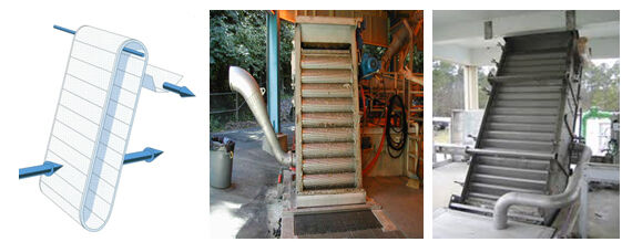
These screens (Figure 4) are commonly used as a coarse, 6-mm headworks screen upstream of a fine or ultra-fine membrane-protection screen to reduce screenings loading. It can be based on stainless steel with punched holes but is more commonly offered with slotted panels.
The screen rotates in the direction of channel flow. Improper screen panel cleaning at the top of the screen (with wash water and brushes) allows debris to carry over onto the clean water side of the screen and channel. This engineering design is therefore not recommended as a fine or ultra-fine membrane protection screen. Through-flow band screens have many moving parts (connective chain, rollers, bushings, pins, ladder bars, seals, etc.) to service and maintain. Independent testing has shown a capture ratio of 51%−71% (MBR Screening Part 2), limiting its use to headworks screening.
2.3 Pumped-flow rotational drum screens
The pumped-flow rotating (rotary) drum screen (Figure 5) was originally designed to dewater industrial sludge and render wastes. The screens are now commonly used with 3-mm, 2-mm and 1-mm slotted/wedge wire, wire mesh and round-hole apertures for membrane protection at municipal wastewater plants. Because the technology is designed so as to be totally contained, bypassing of debris is eliminated. It is normally the preferred choice for pumped flows under 7 MGD (0.31 m3/s).
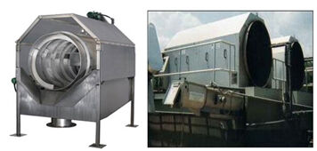
However, the technology is restricted in viable flow rate range, with larger flows requiring two or more drums to process peak flows. Only the back screen panels are submerged in the wastewater at any one time due to the incline of the panels. Slotted screen panels are often used to maximize flow and reduce headloss, but such panels may be insufficiently rigorous for membrane protection since they often allow cotton and hair filaments to pass through the slotted wedge wire spacing. They are more appropriate for high solids concentration and low flows rather than the converse.
2.4 Gravity-flow, rotational drum screens
These screens (Figure 6) significantly reduce bypassing of screenings, reducing the volume of uncaptured material, since they can be sealed to accommodate 1-mm, 0.5-mm and 0.25-mm apertures for ultra-fine screening capabilities. The integral screw removes solids to a washing and compacting system that provides an all-in-one screening and screenings-handling system. Servicing the submersible drum and parts is often accomplished with a tilting mechanism that brings the drum to the deck level for repairs. When operated at the appropriate entry, screen panel and exit velocities, the drum screen is extremely efficient. Single screens are well suited for fine and ultra-fine screening up to 12 MGD (0.53 m3/s or less).
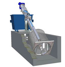
On the other hand, this technology has many moving parts to service and maintain compared to single- and double-entry drum screens that operate on a rack-and-pinion drive. The screen bearing is always submerged in wastewater and needs replacing every 3−3.5 years of service. It does not scale up well due to the angle and limited panel-to-water surface area coverage.
2.5 Centre-flow and dual-flow band screens
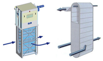
These screens are capable of zero carry-over and by-pass of screenings. They have the highest independently-tested capture ratio of all screens when compared to other travelling band screens, and are used universally at both the headworks and as a membrane protective screen. These screens can be fabricated with 10-mm, 6-mm, 3-mm, and 2-mm round hole aperture screen panels, and can process flows up to 120 MGD (5.26 m3/s) with a 6-mm aperture, and 60 MGD (2.63 m3/s) with 3-mm and 2-mm apertures. However, these technologies have many moving parts (connective chain, rollers, bushings, pins, ladder bars, seals, etc) requiring servicing and maintenance, with the seals requiring regular inspection and replacement. While this type of screen can be employed with 1-mm aperture screen panels, this is not recommended due to the seal tolerance limitation with this design.
2.6 Single-entry, double-entry and duet drum screens
These screens (Figure 8) offer the advantage of only having two moving parts: the rack-and-pinion drive and bearings. They are therefore easy to maintain and service, since there are no moving parts submerged in the wastewater. The seals are in full contact with a thick polyethylene sheet barrier bolted to the civil wall; sealing can be as low as 0.15 mm. Single-drums are capable of processing 800 MGD (35 m3/s) with 6-mm aperture screen panels and 400 MGD (17.5 m3/s) with 1-mm or 0.5-mm aperture screen panels.


Duet drum screens provide coarse and fine/ultra-fine screening in one drum configuration. The duet uses the same simple low-maintenance rack-and-pinion drive as the large single- and double-entry drum screens. With varying depth sloped tanks, duet drums can remove grit from the wastewater, as well as screenings, down to 0.5 mm. The duet can screen flows up to 20 MGD (0.88 m3/s). The technology often becomes the most cost effective and efficient choice since it replaces one coarse screen, one grit removal system and two fine or ultra-fine screens of duty/standby configuration, reducing civils costs and footprint.
However, the large single- and double-entry drum screens do not scale down well economically. They are normally only considered when flow rates exceed 50 MGD (2.2 m3/s) with 6-mm apertures and 25 MGD (1.1 m3/s) with 2-mm, 1-mm and 0.5-mm apertures, or when competing economically against three or more other screens of different design. This screen often requires channels exceeding 10 ft in depth. The duet drum screens are challenged when solids loadings exceed 8.0 cu.ft. per MGD, whereas the duet drum becomes more economically competitive at flows exceeding 3.5 MGD (1.5 m3/s) or when they are replacing multiple screens and a grit system.
3. Summary
In Part 1 of this two-part article, we have provided a summary of the different types of MBR screens available and in use today. Screening represents perhaps the most pivotal component of a membrane bioreactor-based treatment scheme for municipal wastewater treatment.
Appropriate selection and sizing, along with proper maintenance, of the screen is of critical importance in sustaining operation of the plant. This includes the selection and O&M of the primary coarse screen and grit removal technology, since this reduces the load on the fine screen and thus protects both the fine screen and the downstream membrane.
As with the membrane itself, the velocity through the screen – analogous to the flux through the membrane – is the key design parameter and, as with the membrane itself, there is little financial justification for under-specifying the screen on this basis given the potential impact on operational costs. MBR Screening Part 2 addresses the operational factors to consider when selecting an MBR screen.


