Sidestream tubular MBR membranes: a summary of commercial products

Simon Judd
In this final part of three features exploring the MBR membrane market, Simon Judd summarises characteristics of some of the commercially-available tubular membrane modules used in sidestream MBRs, and compares the key characteristics of this process configuration with immersed membranes.
Simon is a Director of Judd Water & Wastewater Consultants, and co-owner of The MBR Site and SludgeProcessing.com.
1. Process configuration and history
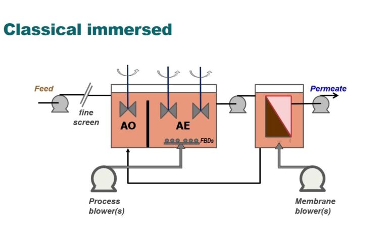
Multi-tube (MT) modules are used for sidestream MBRs (sMBRs), called 'out of basin' MBRs in the US. In this MBR process configuration the membrane is external to the bioreactor and a pump used to circulate the mixed liquor through the membrane channels. This configuration pre-dates the now more widespread immersed MBR, which employs flat sheet (FS) and hollow fibre (HF) membranes. A brief explanation of the MBR process configurations is provided schematically below.
Membrane bioreactor configurations
Sidestream MBRs were originally developed in the late-1960s/early-1970s by Dorr Oliver in the US – some 20 years-or-so before the immersed membrane systems were first commercialised. The Dorr Oliver Membrane Sewage Treatment (MST) system employed a flat sheet membrane, as did the sMBR technology developed by Rhone Poulenc and installed at a number of buildings in Japan in the 1990s. But at around this time sMBRs fitted with MT modules were already being implemented in Europe by Wehrle Environmental for landfill leachate treatment.
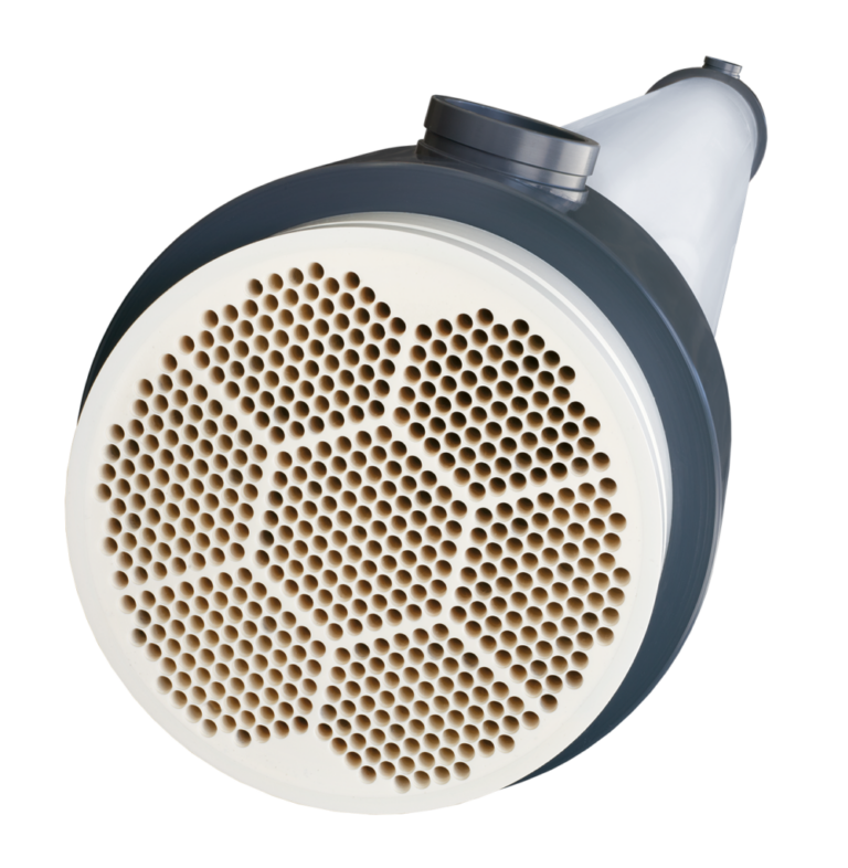
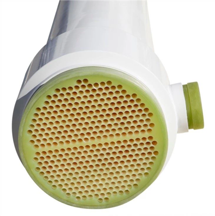
Currently almost all sMBRs implemented for wastewater treatment employ MT membrane modules (Fig. 1). This MBR membrane configuration is currently the only one which can be considered as standardised in terms of the overall module dimensions, commonly supplied in a cylindrical casing 8” (200 mm) in diameter and 3 m in length. The modules comprise a bundle of tessellated membrane tubes. The mixed liquor is conveyed along the length of the inside of these tubes with the permeate flowing from inside ('lumen side') to outside ('shell side').
2. Module orientation
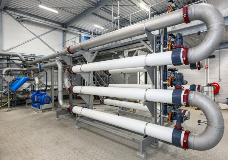
There are two module orientations for sMBRs: horizontal and vertical. The classical 'pumped' sMBRs employ horizontal modules. To provide a high conversion for a single passage of sludge pumped along the membrane surface, the modules are mounted as a series of loops in a serpentine arrangement within the membrane skid (Fig. 2). The total retentate path length, including the semi-circular connectors, therefore exceeds 20m.
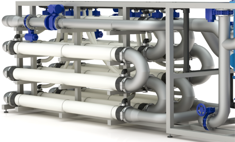
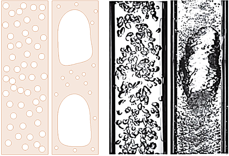
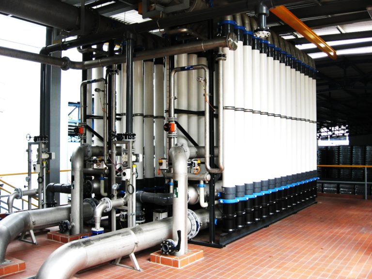
For sMBRs employing vertically-oriented modules the mixed liquor is air-lifted through the membrane channels by introducing large air bubbles into the mixed liquor entering the modules. The air forms 'slugs' which fill the membrane channel (Fig. 3). This flow regime, termed 'slug flow' where the mean free bubble diameter is larger than the tube diameter, is known to generate higher fluxes than those attained from smaller bubbles ('bubbly flow'). For these air-lift systems the modules in the array are discrete (Fig. 4), rather than interconnected in a serpentine arrangement as with the pumped systems.
3. Commercial providers
3.1 MT membrane modules
Selected MT membrane suppliers and the product specifications are listed below. The pore dimension dp is rated either as the size in nm or the molecular weight cut-off (MWCO) in kDa. All the providers listed offer module products in the standard size of 200 mm diameter and 3 m in length, and based on a PVDF membrane material of 30 nm pore size. There are a number of other MT membrane module suppliers whose products are not necessarily targeted at sMBR applications.
| Supplier | Co. | Model ID | Material | dp or MWCO | ID, mm | L, m | D, mm | Area, m2 |
|---|---|---|---|---|---|---|---|---|
PVDF Polyvinylidene fluoride; MWCO molecular weight cut-off in kDa | ||||||||
| Berghof | Ger | MO 83G I8 V | PVDF | 30 nm | 8 | 3 | 207 | 27.2 |
| Berghof | Ger | MO 84G I8 V | PVDF | 30 nm | 8 | 4 | 210 | 36.7 |
| Berghof | Ger | MO 103G I8 V | PVDF | 30 nm | 8 | 3 | 260 | 40 |
| Berghof | Ger | MO 104G I8 V | PVDF | 30 nm | 8 | 4 | 260 | 53.4 |
| PCI Membranes | UK | A8 | PVDF | 20−450 kDa | 8 | 3, 4 | 200 | 27, 36 |
| Pentair | US | Compact 27, 33 | PVDF | 30 nm | 8, 5.2 | 4 | 200 | 27, 33 |
| RisingSun | Ch | TG-30nm-8830 | PVDF | 30 nm | 8 | 3 | 200 | 27.2 |
3.2 sMBR technologies
In the sMBR space there are providers of systems that are not necessarily specific to a membrane product. This is because the MT membrane modules are of a standard dimension, such that one MT membrane module product can be substituted for another without demanding changes to the housing, pipework, or other infrastructure component. This presents an advantage of pumped sMBRs over the immersed configuration, where some modifications are often required if one product is to be substituted for another.
MT sMBR technologies generally have three modes or designs:
- a) conventional pumped (horizontal membrane modules),
- b) low-energy pumped (horizontal membrane modules), and
- c) air-lift or air scour (vertical membrane modules).
The conventional pumped configuration is employed for both aerobic and anaerobic systems (AnsMBRs), and is often favoured for treating small effluent flows from industrial installations. This configuration incurs the highest membrane separation specific energy consumption (SEC in kWh per m3 permeate) of all the MBR technologies, but also incurs a low footprint because of the high flux attained (in excess of 150 LMH for the most treatable effluents, such as those from vegetable processing or beverage production).
The low-energy pumped system is based on the same configuration but employs a lower crossflow velocity (CFV) and a commensurately lower operating flux. This increases the required membrane area but also reduces the SEC.
The air-lift configuration (A-LsMBR) permits lower-energy operation for filtration, whilst also demanding the pumping of both the air and the sludge to maintain operation of the membrane. This technology, fitted with vertically-aligned modules, competes with FS and HF immersed systems in the municipal wastewater treatment space. The energy efficiency is comparable but the membrane system costs are normally higher.
Examples of suppliers and their technologies are given in Table 2. In the case of Berghof the company have now developed software (B-SMART) which can automatically adjust the CFV to the optimum value to minimise the SEC.
| Supplier | Pumped | Low-energy pumped | Air-lift |
|---|---|---|---|
*Now replaced by the B-SMART® intelligent software | |||
| Aquabio/Freudenberg | AMBRTM | AMBR LETM | - |
| Berghof | Bioflow* | Biopulse* | Bioair DS |
| Dynatec | HiRateTM | - | DynaliftTM |
| WEHRLE | BIOMEMBRAT® | BIOMEMBRAT-LE | |
4. Sidestream vs immersed: pros and cons
The vast majority of MBRs installed worldwide are configured with immersed membranes, on the basis of their lower energy consumption and overall cost. However, sMBRs offer specific advantages relating to their robustness and adaptability (Table 3). These facets mean that they tend to be selected for small flows of challenging industrial effluents, where the energy penalty may be counterbalanced by the operational flexibility and control.
| Immersed | Pumped sidestream |
|---|---|
| Non-standardised modules | Standardised ~200 mm-diameter MT modules |
| Generally lower energy (<0.5 kWh/m3) for membrane component | Generally higher energy (>0.5 kWh/m3) for membrane component |
| Lower fluxes/higher membrane area requirement | Higher fluxes/lower membrane area requirement |
| Lower specific membrane area cost (cost per unit area) | Higher specific membrane area cost (cost per unit area) |
| Fouling/clogging controlled by air scour | Fouling/clogging controlled by crossflow liquid scour |
| Control of shear limited by random path of air bubbles across membrane surfaces | Precise control of shear possible if variable-frequency drive (VFD) motors for pumps are fitted |
| Small chemical risk to biomass from clean-in-place chemical cleaning | In-situ chemical cleaning of membranes possible without any chemical risk to biomass |
| Downtime for maintenance generally higher, particularly for membrane module replacement | Downtime for maintenance generally lower, particularly for membrane module replacement |
| Not generally desirable or possible to bring individual modules off- and on-line | Loops can be readily brought on- and off-line according to hydraulic loading |
| Limited operational flexibility with reference to flux | Switching between high-flux/high-energy and low-flux/low-energy possible if VFD motors fitted |
MT sMBR technologies generally have three modes or designs:
- a) conventional pumped (horizontal membrane modules),
- b) low-energy pumped (horizontal membrane modules), and
- c) air-lift or air scour (vertical membrane modules).
The conventional pumped configuration is employed for both aerobic and anaerobic systems (AnsMBRs), and is often favoured for treating small effluent flows from industrial installations. This configuration incurs the highest membrane separation specific energy consumption (SEC in kWh per m3 permeate) of all the MBR technologies, but also incurs a low footprint because of the high flux attained (in excess of 150 LMH for the most treatable effluents, such as those from vegetable processing or beverage production).
The low-energy pumped system is based on the same configuration but employs a lower crossflow velocity (CFV) and a commensurately lower operating flux. This increases the required membrane area but also reduces the SEC.
The air-lift configuration (A-LsMBR) permits lower-energy operation for filtration, whilst also demanding the pumping of both the air and the sludge to maintain operation of the membrane. This technology, fitted with vertically-aligned modules, competes with FS and HF immersed systems in the municipal wastewater treatment space. The energy efficiency is comparable but the membrane system costs are normally higher.
Examples of suppliers and their technologies are given in Table 2. In the case of Berghof the company has now developed software (B-SMART) which can automatically adjust the CFV to the optimum value to minimise the SEC.
Some of the most significant advantages of sMBRs arise from the location and discreteness of the membrane modules. Membrane modules positioned external to the tank are more readily accessed than those submerged in a tank, making it easier to extract and/or replace individual modules. Also, all sMBR technologies allow energy management through the adjustment of the CFV or the shutting down of some of the modules during periods of low flow and readjusting/restarting when normal or high flow commences. This can be done without any risk of impairment of the mixed liquor quality.
The relative footprint of each configuration and module can be estimated from the packing densities of the modules and the module spacing. Packing densities for the Flat Sheet and Hollow Fibre membrane modules have already been determined. For these configurations the membrane area per unit floor area (FA) is dependent on the degree of stacking of the modules, with FA increasing with stacking.
| Configuration | Flux, m/d | FA mod, m2/m2 (a) | FA tank or skid, m2/m2 (b) | SOR equiv., m/d |
|---|---|---|---|---|
abased on mean values from commercial FS and HF modules; bassuming representative spacing or arrangement of modules in tank or on skid; cbased on mean data from FS modules; dbased on mean data from HF modules; ebased on operational parameter and product dimension values provided by Berghof | ||||
| FS, rigid panel | 0.5 (c) | 221 (c) | 55 | 28 |
| FS, composite | 0.5 (c) | 310 (c) | 74 | 37 |
| HF | 0.5 (d) | 427 (d) | 171 | 85 |
| MT pumped | 2.6 (e) | 45 (e) | 65 (e) | 170 |
| MT air-lift | 1.2 | 866 | 162 | 194 |
According to the assumptions made in Table 4, where the flux and footprint figures for the FS and HF membrane configurations are based on averaged values at the maximum overall module height, the SOR for the conventional pumped sMBR technology is 2−6 times that of the immersed configuration. Since the MLSS employed also tends to be higher (12−15 g/L cf. 8−10 g/L for an immersed HF technology), leading to smaller biological tanks, the overall footprint for the sidestream configuration is commensurately lower. Against this, both the SEC and the specific membrane cost (in $/m2) for a pumped sMBR is higher than for the iMBR.
5. Other sMBR membrane module materials
Polymeric MT membrane products have been employed for industrial effluent, based on pumped sidestream MBR technology since the early 1980s. There are also a growing number of ceramic MT and multi-channel (MC) products though it appears these are not yet widely established as sMBRs. An example of a ceramic membrane product which has been implemented for sMBRs in the past is the Likuid Nanotek technology.
6. Summary
The sMBR technology is of historical significance, since it represents the MBR configuration first implemented. sMBR technologies were originally based on flat sheet membranes, but the MT configuration is now the most widely used in sMBRs. While considered viable primarily for industrial effluents, the air-lift mode finds use in municipal wastewater treatment. For both pumped and air-lift modes, the footprint incurred is significantly less than that for the immersed configurations. Whilst incurring a higher energy consumption than iMBRs, sMBRs offer a degree of simplicity and robustness associated with the accessibility of the membrane and the pumping of the mixed liquor through the cylindrical membrane channels.


