Down by the river: the MBR at Woolston WwTW


With its small footprint and proximity to residential areas, upgrading the works at Woolston presented a bit of a challenge.
Simon Judd is given a guided tour of Southern Water’s 37 MLD MBR-based WwTW down on the UK south coast.
1. Site layout
Southern Water’s Woolston wastewater treatment works represents a project envisaged and implemented with a great deal of care and attention. The small available footprint and the proximity of residential housing demanded a robust and visually appealing structure, as well as tight controls on both liquid and odour emissions.
The highly unusual contoured steel cladding used (Fig. 1) was originally subject to rigorous wind tunnel testing, based on a 3D-printed 1:300 scale model. The works includes scrubbers for treating off gases prior to venting and, of course, treatment of the sewage itself is based on MBR technology.
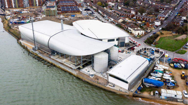
The site is situated on the banks of the river Itchen: you could, if so inclined, hop on a boat from the site’s riverside boundary by the storm tank and head across river to Ocean Village for a bite to eat and a bit of shopping. For a site of its capacity – currently 37 MLD but with plans to expand – it’s pretty tight, with just 62 hectares of available area. This being the case, it’s as well that there’s only 3−4 operators required to run the site; parking for more than four vehicles could be a bit of a challenge.
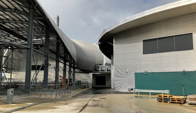
The three main buildings which make up the site – respectively housing the primary clarification, the secondary biological treatment, and the sludge processing – are within a stone’s throw of one another (Figs. 2 and 3). And you’d not need a particularly strong arm.
Fig. 2. A view from within the Woolston MBR site
2. Preliminary and primary treatment
A lot of the action goes on beneath the surface at this site. This includes both the underground storm tanks, converted from the original aeration tank of the ASP and providing several hours of equalisation, and the 25 mm CSO (combined sewage overflow) screens. The coarse-screened sewage then undergoes further screening through three sets of 6-mm escalator fine screens (Fig. 4) before being fed into two cylindrical FOGG tanks (Fig 5), where combined grit and FOG (fats oils and grease) removal takes place. The grit is classified (Fig. 6), i.e. separated from the organic matter, by washing before being discharged as a substantially odourless aggregate product.
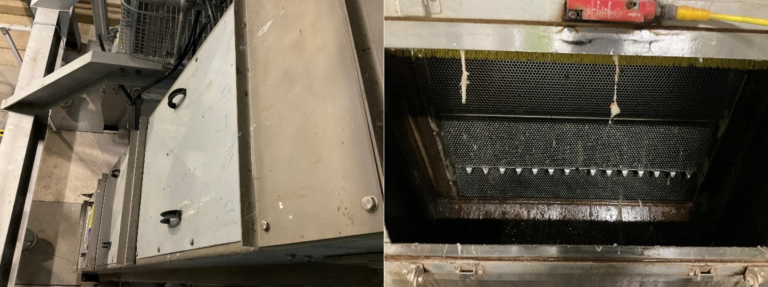
Fig. 5. View from the top, starting with the two FOGG tanks and finishing with the lamella tanks
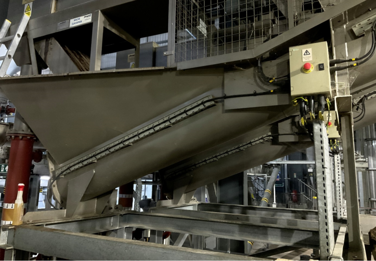
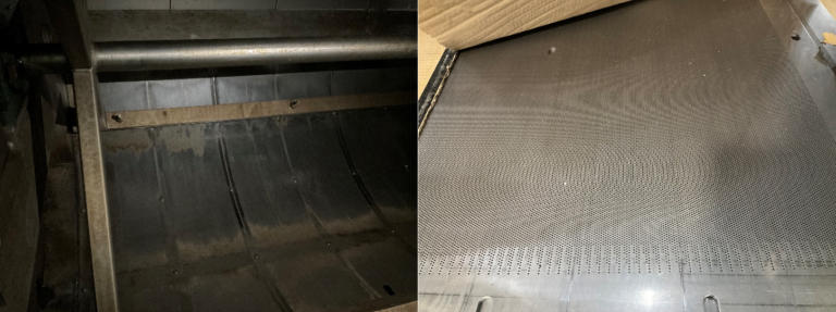
From the FOGG tanks the wastewater passes to the primary sedimentation step, which comprises three sets of lamella plate separators (Fig. 5). These plates are air-scoured daily to limit the build-up of solids on the plates. The wastewater is then directed to the 1.5-mm ultrafine drum screens (Fig. 7) before leaving the building and heading next door for secondary biological treatment.
3. Biological treatment and membrane separation
Biological treatment − the engine room of the whole process − is based on the established MLE (modified Ludzack-Ettinger) configuration for nitrification−denitrification. It comprises three anoxic lanes sandwiched between four aeration lanes and eight MBR trains (Fig. 8), with a recycle ratio of 4 between the membrane and process tanks.
Fig. 8. A short walk across the top of the anoxic tanks, starting from the aerobic lanes on the right and ending up at the membrane tanks on the left
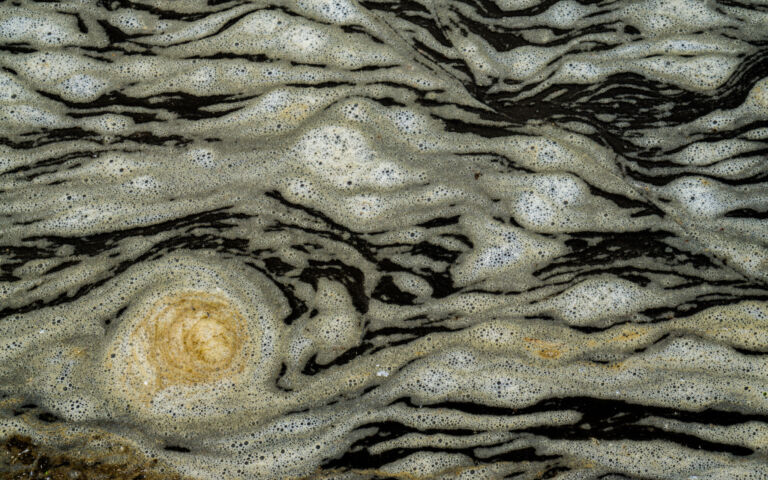
As with the rest of the plant, the tanks are fitted beneath metal or concrete flooring. A peek under one of the sheet metal floor plates reveals the satisfying sight of an aerated, healthy-looking mixed liquor (Fig. 9).
Fig. 9. The mixed liquor in the aeration lanes
The membrane tanks (Fig. 10) are fitted with Koch Puron PULSION LE44 modules, with five modules placed in each of the eight trains. These modules are capable of providing a maximum membrane area of 1,914 m2 from 44 sub-modules or rows (each comprising 8 membrane bundles), and thus 76,560 m2 in total for the complete installation. The modules fitted at Woolston currently contain 36 rows (and so 1,566 m2 per module, or 62,640 m2 in total). Each train is provided with its own blower and permeate pump (Fig. 11).
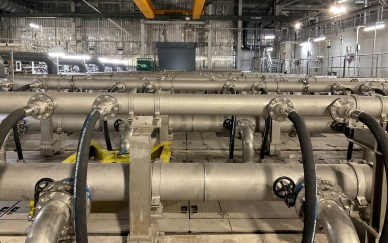
Fig. 11. The membrane blowers and permeate pumps
At the peak flow of 37 MLD, the total installed membrane area implies a gross flux of 24.5 LMH, or 28 LMH for seven lanes operating (i.e. N-1). However, the mean flow is around half this value.
The membranes are backwashed with air scouring every 10 minutes. A 30-minute chemically-enhanced backwash (CEB) with hypochlorite is conducted every two days, and a citric CEB every 60 days, each taking around 45 minutes per module to complete. There are also annual recovery cleans where the whole lane is emptied and filled with hypochlorite, and the membranes allowed to soak for a few hours.
4. Sludge and odour management
The primary and secondary sludge stream are directed to two 735 m3 sludge storage tanks which feed the sludge processing plant.
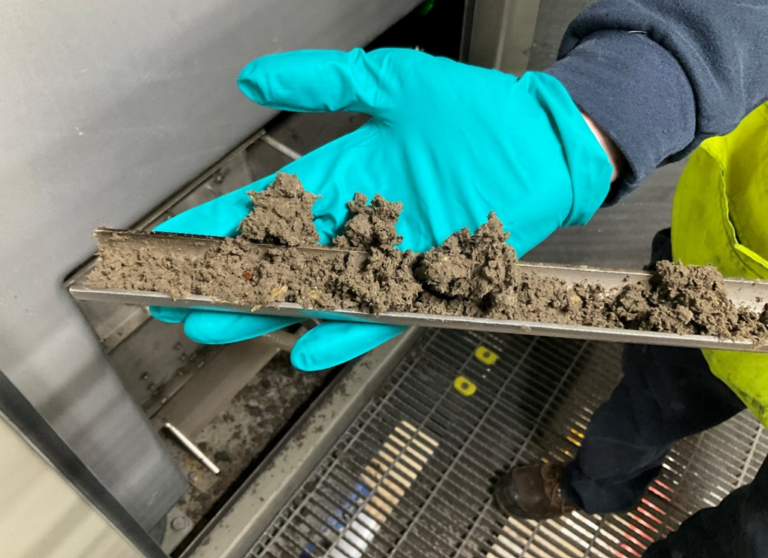
A sludge flow of around 35 m3/h (and so ~4% of the feed wastewater) is dosed with a cationic polyacrylamide flocculant before being fed to a bank of three centrifuges (Fig. 12). The feed sludge is a blend of primary sludge at ~3−4% dry solids (DS) and WAS (waste activated sludge) at 1−1.2% DS, and is dewatered to a DS concentration of 25−30% in the cake product (Fig 13). The cake is then pumped to the sealed containers just outside the building, ready for shipping off site.
Fig. 12. The bank of three centrifuges
The odorous air extracted from the primary building plant is directed to the odour control plant, where it passes through a wet scrubber (fed with 47% caustic soda) and downstream carbon filters before being vented to the atmosphere. As with all properly-operated suspended growth biological processes, there is no odour issue with the secondary stage: this building requires no ventilation.
5. Overall
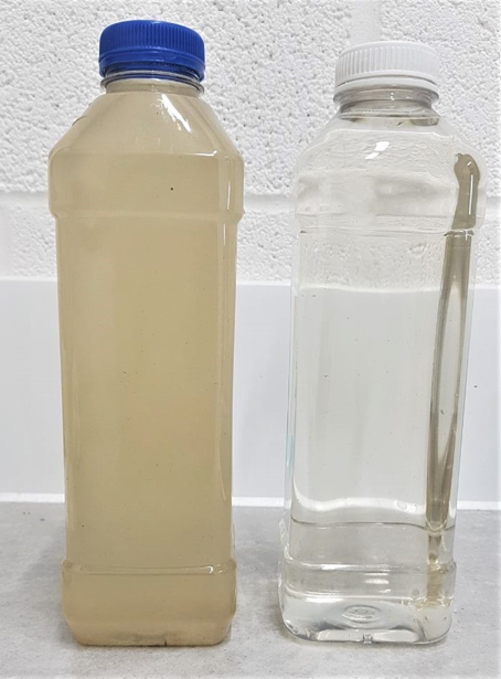
There have apparently been few problems of any note since start-up of the installation in May 2019. The process affords a 70% increase in capacity compared with the previous works on the site, with plans to increase this further in the future. BOD is generally removed to below limit of detection, nitrification is >99% complete, the effluent TN is ~10 mg/L and – naturally – there is complete clarification (Fig. 14). Despite this there is plenty of redundancy, with duty-standby for most of the process steps. It seems that the most significant challenge experienced at the site was that posed by some pigeons that obviously took a liking to the place and needed to be encouraged to leave.
MBRs are certainly not a panacea and should never be regarded as the only choice for upgrading a wastewater treatment works. However, in the case of the Woolston site, with its miserly footprint within a residential area combined with a tight discharge consent, it presents a sensible solution and, by all accounts, its implementation has gone pretty smoothly.
Acknowledgements
The authors would like to thank Greg Clark and Graeme Lea at Southern Water for organising the visit, and Steve Clarke and Darren Isaacs for showing us around on the day.
