Footprint − the factors governing size in an MBR

Simon Judd has over 35 years’ post-doctorate experience in all aspects of water and wastewater treatment technology, both in academic and industrial R&D. He has (co-)authored six book titles and over 200 peer-reviewed publications in water and wastewater treatment.
Contrary to the mantra offered to insecure men in the 1970s, size is important. Shaving a few millimetres or grams off the dimensions or mass of a mobile phone, for instance, while providing the same functionality, is often justification enough for a price hike. Designing sufficient space in the boot of a car to allow a set of golf clubs to be stowed can open up a whole new market. Fitted wardrobes provide substantially more space than free-standing ones.
And of course, sometimes there just isn’t enough room − as anyone who’s ever packed the suitcases or loaded up the car for a two-week family break must surely appreciate. In the case of wastewater treatment works, particularly on an industrial site, small is often not only beautiful but a pre-requisite governing process selection.
It's their compactness that is one of the beauties of MBRs and often leads to their selection as the preferred technology. Crucially, MBRs permit a higher MLSS concentration than a conventional CAS process, and this means proportionately smaller biological process tanks. The MLSS concentration is only then limited by the combined constraints of reduced oxygen transfer and the filterability of the mixed liquor.
So what about the membrane separation part? First of all, it's important to appreciate that there are two bases for measuring footprint: by area and by volume.
The flow per unit floor area (FA) is normally the most important and takes units of length per unit time − the same as velocity. For conventional clarification this is sometimes termed 'the surface overflow rate' (the volumetric flow rate per unit surface area, 'surface area' being pretty much the same as the footprint). For a media filter, it's called the approach (or superficial) velocity or filtration rate. It can be as low as 0.1 m/h for a slow sand filter (necessarily so since an SSF combines media filtration with biological treatment) to more than 120 m/h for a proprietary ballasted clarification technology.
The flow per unit volume (FV) takes units of inverse time and is simply the inverse hydraulic residence time. FV equates to FA divided by the height. These two terms formed the basis of a comparison between different unit operations for treating produced water on an oil platform, where room is pretty scarce.
None of these processes are MBRs, but it might be of interest to those working in the oil industry. Suffice to say that membrane technology was nip-and-tuck with induced gas flotation.
Footprint is defined by three things
In the case of membrane technology, footprint is defined by three things:
- how fast the water flows through the membrane, given by the flux in L m-2 h-1 or m day-1
- how densely packed the membranes are in the module, defined by the volumetric packing density in m2 membrane per m3 volume
- how well the membrane modules tessellate, i.e. pack together without leaving gaps.
Given that the flux is largely determined by the feed water and/or, for an MBR specifically, MLSS characteristics, it is mainly the packing density and module tessellation which define the footprint of the membrane tank. Immersed modules are almost all rectangular, so are very space efficient with reference to tessellation. The packing density depends partly on the membrane configuration, with the rigid flat sheet (FS) design tending to be less densely packed − and thus having a lower FV − than either the composite flat sheet membranes or the hollow fibres (HF).
FA can be increased either by making the membrane module taller or by stacking. However, stacking increases the specific aeration energy demand because the aerator has to be placed lower in the tank and so works against a larger hydraulic head. On a practical level, it also makes the lower module less accessible.
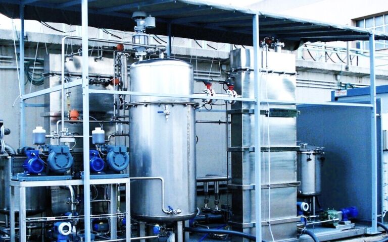
Pumped sidestream modules are normally standard 8” cylinders which have to be interconnected in a serpentine manner to form 'loops'. Although higher fluxes are obtained, the overall FV is much lower than for the immersed case due to the necessary spacing of the modules. Against this, the sidestream configuration offers the advantage of flexibility and very narrow loops which can slot in to the most confined of spaces: I once saw one on an industrial site sandwiched between the outside wall of a hangar and a chain-link fence boundary.
Of course, the gain in space through selecting a more densely-packed membrane module may be only marginal. And if the gaps between the membranes are smaller, then the risk of fouling and clogging may be greater. But, ultimately, it all comes down to the folding stuff. If time is money, then space runs it a pretty close second.


