MBR implementation in California: the WRRF at San Luis Obispo

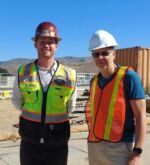
Simon Judd (right, with Patrick McGrath, City of SLO) reports from a visit in October 2023 to the Water Resource Recovery Facility serving the City of San Luis Obispo in California
1. Background
The City of San Luis Obispo (SLO) Water Resource Recovery Facility (WRRF) has a design mean flow capacity of 5.4 MGD (20.5 MLD), peaking at >20 MGD (>75 MLD) during storm flows. The facility collects wastewater from the City, California Polytechnic University, and the San Luis Obispo County airport. The treated effluent is discharged to the SLO Creek, with around ten percent currently being diverted for non-potable reuse.
The ongoing upgrading of the works from a classical activated sludge (CAS)-based treatment scheme to an MBR with downstream UV disinfection has presented challenges often encountered when new process technologies are being implemented at an established site with existing historical infrastructure. At the SLO WRRF, the activated sludge process tank and chlorine contact tank both date back to 1991, the primary clarifiers to 1941, two of the digesters to 1941 and 1951, and the original anaerobic digester to 1926. In all of these cases, the original concrete is in good order, such that both investment costs and environmental footprint can be reduced by reusing or repurposing these assets. Upgrading then becomes a matter of determining which of the assets can be employed in the modified treatment scheme.
2. Wastewater treatment
The upgraded full treatment scheme (Fig. 1) for the main wastewater flow at the site comprises:
- Equalisation for ~2 days at the mean design flow rate of 5.4 MGD
- Screening to 6 mm using multi-rake bar screens (Fig. 2), rated at 16 MGD (60 MLD)
- Degritting using two duty-only rectangular detritor tanks (Fig. 3), fitted with Huber Coanda grit classifiers (Fig. 4) for grit recovery and washing, rated at 500 GPM (114 m3/h)
- Dual 80 ft (24 m) diameter primary clarifiers (Fig. 5)
- Fine screening to 2 mm using two duty/standby Ovivo rotary drum fine screens (Fig. 6)
- Process biology based on:
- a 250k gall (946 m3) anoxic zone, with sludge fed back from the membrane tank via the RAS channel at a recirculation ratio of ~3
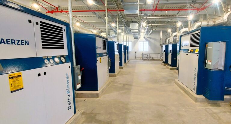
- four 25 m-long aeration lanes with a total active volume of 1.32 MG (5000 m3), fitted with FBDA disc diffusers fed with Aerzen GM50L rotary lobe blowers rated at 3885 SCFM (6235 Nm3/h) (Figs. 7−9)
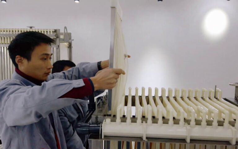
- Mixed liquor filtration in six membrane tanks, each fitted with six cassettes (4 full/2 flex) of 36 (flex) – 52 (full) ZW500 immersed hollow fibre modules (34.4 m2 membrane area)
- Air scour provided by six Aerzen D62S rotary lobe blowers, one per train (Figs. 9−10)
- Membrane CIP provided by hydrogen peroxide (30% stock solution) and citric acid (50%), with maintenance cleans applied twice-weekly and supplemented with quarterly recovery cleans
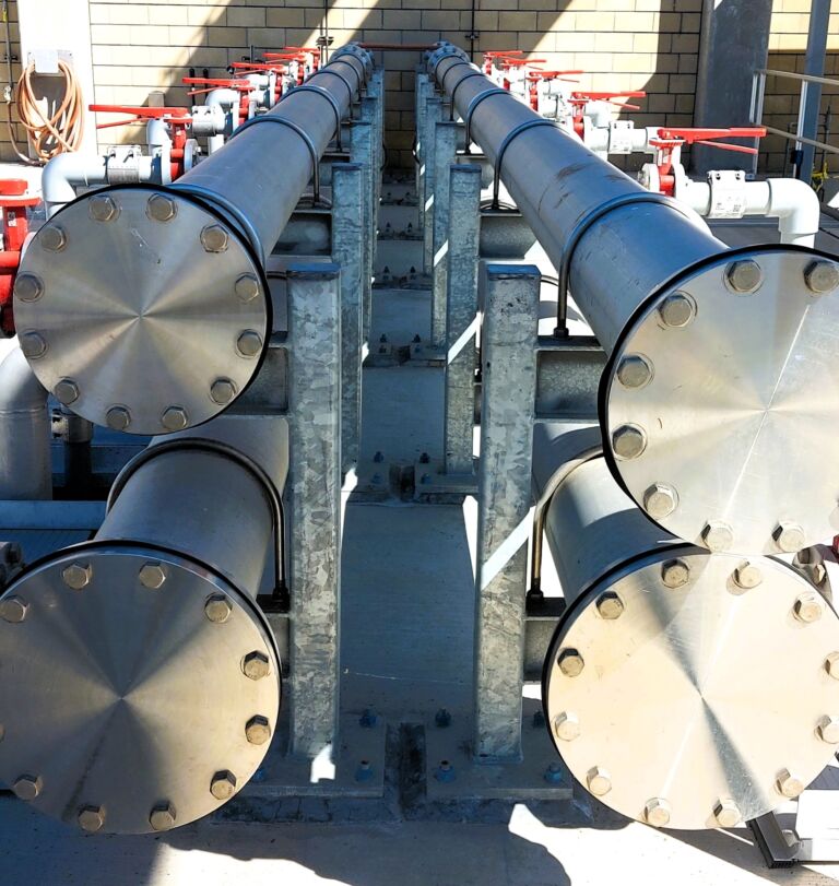
- Disinfection through a bank of nine Wedeco LBX UV reactors, each fitted with 60 lamps (Fig. 11), and
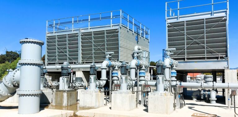
- Cooling to 22.5 °C using a bank of three evaporative heat exchangers (Fig. 12).
For some of the new process technologies, new equipment infrastructure has been required. This includes the membrane tanks, the UV disinfection units and the coolers.
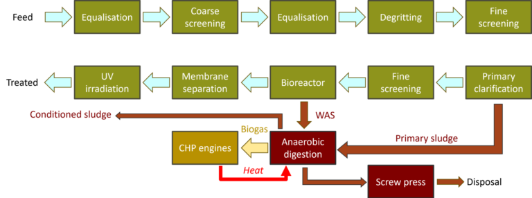
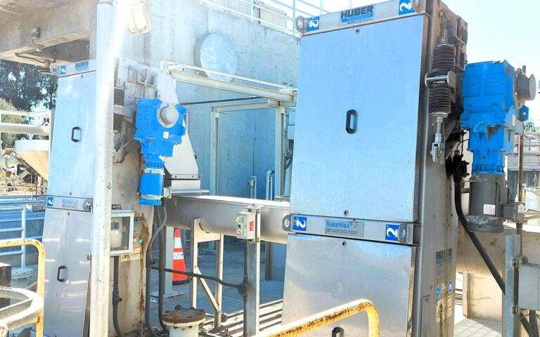
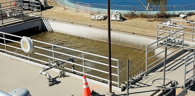
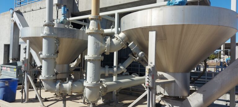

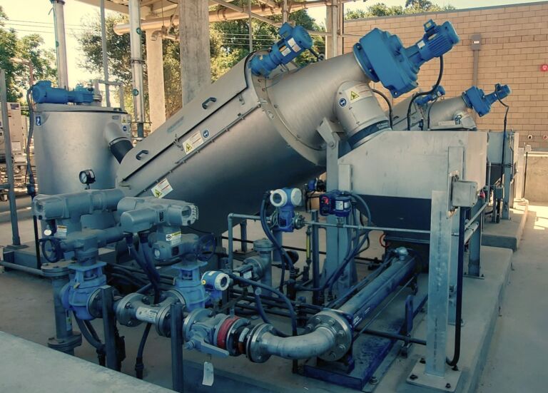
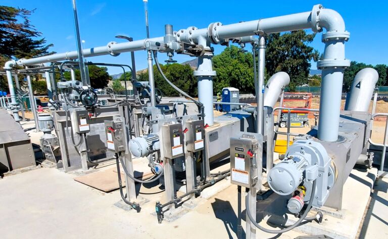
Fig 7. A short walk across the top of the process tanks, starting from the mixed liquor pumps at one end, San Luis Obispo WRRF

3. Residuals management
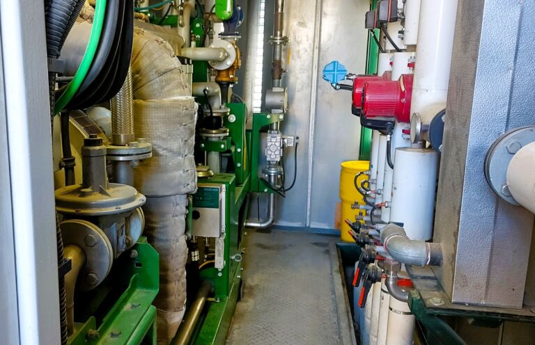
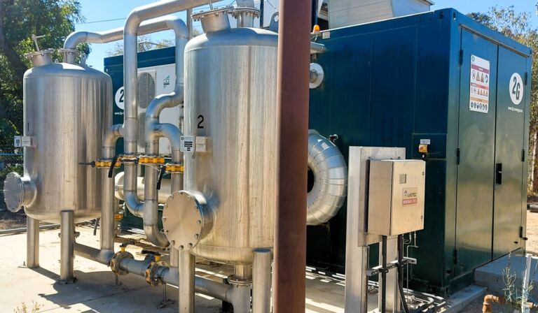
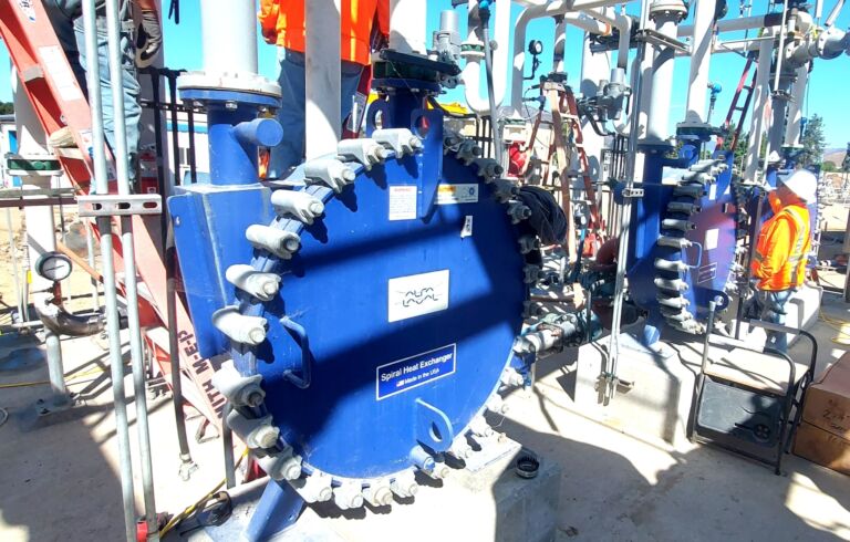
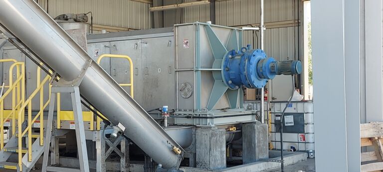
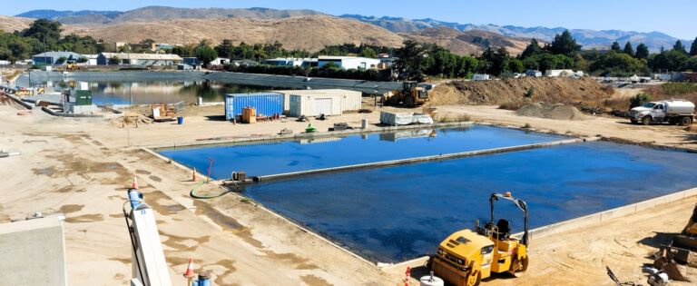
Treatment of residuals (the primary and secondary waste sludge streams) is through anaerobic digestion (AD) in three tanks offering a total volume of 4921 m3 (Fig. 13). The biogas generated is fed to a 2G CHP engine via two conditioning units (Fig. 14). The resultant heat generated is used to pre-heat the sludge upstream of the AD using three spiral heat exchangers (Fig. 15). The AD digestate is then fed to either a screw press (Fig. 16) or a drying bed (Fig. 17).
The original 1920s digester tank has been repurposed as a biofilter for odour control. It is filled with GAC media which provides effective deodourisation of the combined vented streams from the headworks, primary clarifiers, screw press, and fine screens.
Fig 13. The three existing digester tanks, San Luis Obispo WRRF
4. Challenges
As with water and wastewater installations worldwide, SLO WRRF has been subject to the vagaries of inclement weather associated with climate change. One-in-a-hundred-year storms have visited the facility twice in the past five years, necessitating significant remedial efforts on both occasions. Storm protection measures at the site include raising the headworks by half a metre and doubling the EQ volume from 4.5m to 9m gallons. Additional storm protection measures include flood walls around the facility’s headworks and other components, and storm flow programming for coordinating pumps and valves for higher volumes.
A major challenge during the implementation was posed by the existing underground assets. The precise location of the pipes, some of which date back to 1941, had to be painstakingly logged and the new pipework designed and fitted without obstructing or fouling the existing assets. Moving forward, all new buried assets have been included in a BIM (building information model) of the facility; all pipes and duct banks include tracer wire for ease of location.
Solids handling, relating to sequencing and scheduling of the work, had resulted in septic conditions. These conditions impacted on both the treatment processes and the local community due to the generation of odour. This has been addressed through reconfiguring the existing systems and deploying mobile treatment skids to mitigate and remove septic solids. Temporary skids have included a dewatering skid for reducing sludge volumes prior to hauling off site, and a mobile odour scrubber.
The site staff have also come up with an ingenious solution to a familiar challenge at sites with established process technologies: the renewal of components or component parts for obsolete equipment. Rather than face the exorbitant costs and/or long lead times associated with ordering new items, the team have looked to repair the existing equipment by replacing the damaged part with a replica fabricated using a 3D printer. This has only been possible through developing the necessary specialist knowledge and skills in house, but has allowed the repair of obsolete equipment by replacing the affected component by designing and printing a copy within a matter of hours. Examples so far include a fan for a motor, a nozzle for a solenoid valve, and even models of Tardigrades for an outreach programme.
Whilst challenges have been faced in the implementation of the new technologies at the SLO WRRF, few of these have related directly to the MBR technology itself other than higher-than-expected levels of air in the permeate line and adapting the maintenance cleaning schedules from baseline recommendations. Issues have instead been associated with either unusual storm events or system integration issues such as communication and controls coordination with the ultraviolet disinfection system. Otherwise, since the commissioning of the MBR and UV plants in June 2023, staff have observed a significant improvement in the quality of water discharged to the San Luis Obispo creek and delivered across town as recycled water for irrigation.


