Immersed flat sheet MBR membranes: a summary of commercial products

Simon Judd
In this first of three features exploring the MBR membrane market, Simon Judd summarises characteristics of some of the commercially-available immersed flat sheet membranes for wastewater treatment.
Simon is a Director of Judd Water & Wastewater Consultants, and co-owner of The MBR Site and SludgeProcessing.com.
1. Immersed flat sheet membrane and module construction
Immersed flat sheet (iFS) membranes for MBRs have been around since 1991. The earliest example of a commercialised iFS was the Kubota membrane cartridge, which arose from the Aqua Renaissance programme in Japan. This was a national R&D programme dedicated to water reuse and energy recovery which ran from 1987 to 1993, and which was supported by the Japanese Ministry of International Trade and Industry.
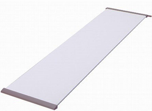
The Kubota cartridge was based on the rigid flat panel configuration, and a number of products based on this principle have since been introduced. Rigid panels employ a 4−6 mm-thick rigid or semi-rigid plastic backing plate (Fig. 1a), normally made of acrylonitrile butadiene styrene ABS, to which the edge of the membrane is welded on both sides of the plate. The backing plate contains a series of grooves which allows the permeate to flow to the edge of the panel where the extraction tube is fitted (Fig. 1b).
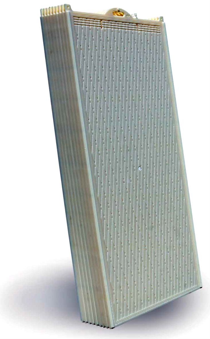
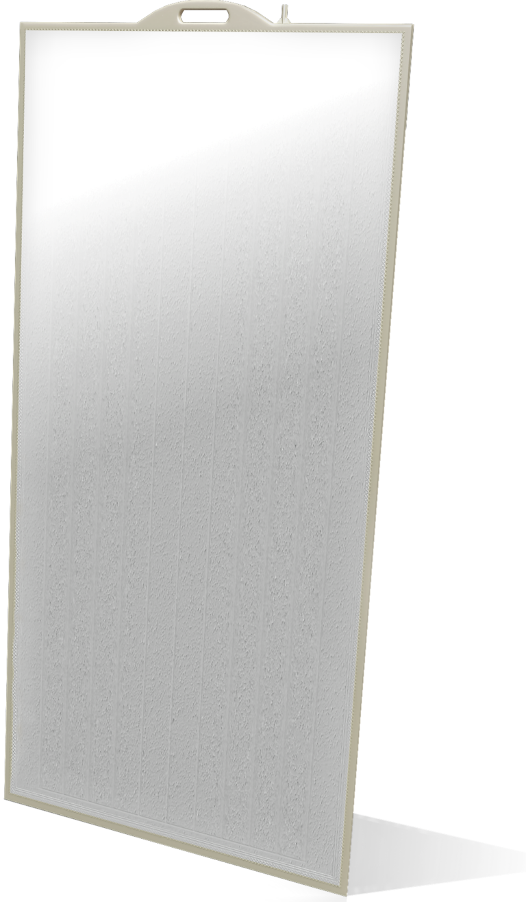
The membrane is separated from the plate by a thin spacer, usually unwoven cloth. Water flows from outside to inside the panel through the spacer material and the permeate is collected from the permeate outlet tube(s). The panels are loaded into a ‘cassette’ (Fig. 2a), which holds a large number (50−200) of panels, and the permeate outlet tubes from each panel (Fig. 2b) are all fed to one or two manifolds at the edge(s) of the unit.
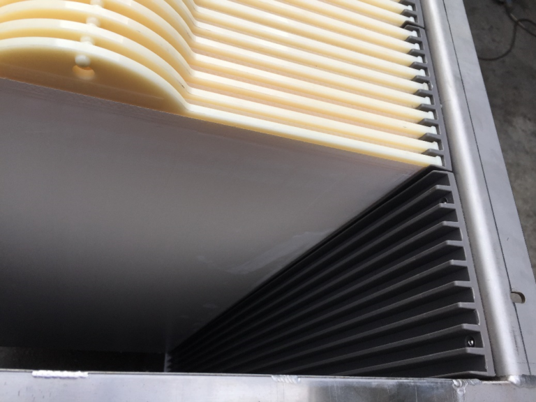
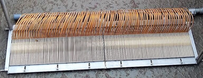
Rigid panel iFS MBR membranes are still offered today from various suppliers. The design permits individual panels, and/or extraction tubes, to be replaced or repaired if damaged. Also, if the sludge level in the tank is lowered to the point where the extraction tubes at the top of the module are visible, it is possible to discern whether an individual panel is damaged by the appearance of the fluid in the extraction tubes, which are translucent. The fluid is normally clear; if significantly turbid then this indicates the direct passage of particles or colloidal matter from the mixed liquor into the permeate line.
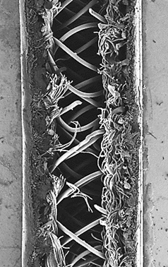
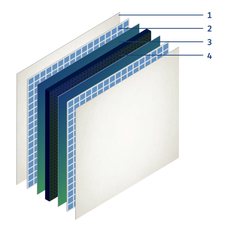
An alternative to the rigid panel design is the composite membrane material, first introduced in 2005 by Microdyn Nadir (now part of MANN+HUMMEL). Unlike the rigid panel design, the spacer (Fig. 3a) in the composite membrane acts both to separate the two membrane sheets to which it is attached (Fig. 3b) and permit the flow of permeate to the permeate manifold. This means that the spacer is not required to provide significant mechanical strength, and needs only to have roughly the same water permeability as the grooves in the backing plate of the rigid panel design. The iFS composite membrane can therefore be flexible and the spacer significantly thinner than the rigid panel backing plate (1.5−2.5 mm compared to 4−6 mm). The permeate is collected from either the centre (Fig. 4a,b) or the side(s) (Fig. 4c) of the module.
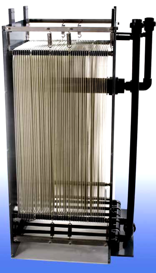
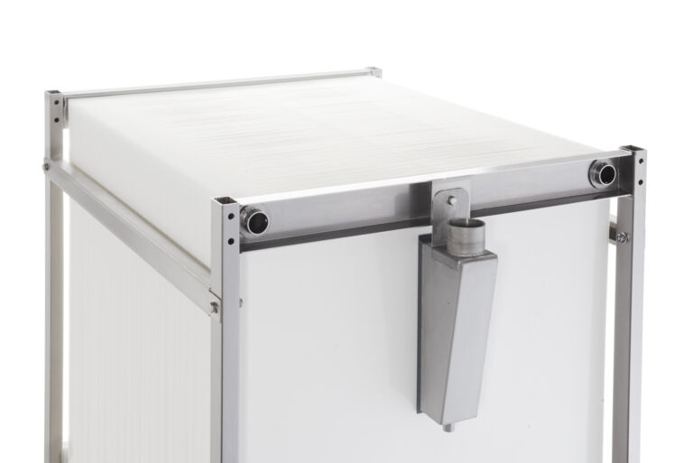
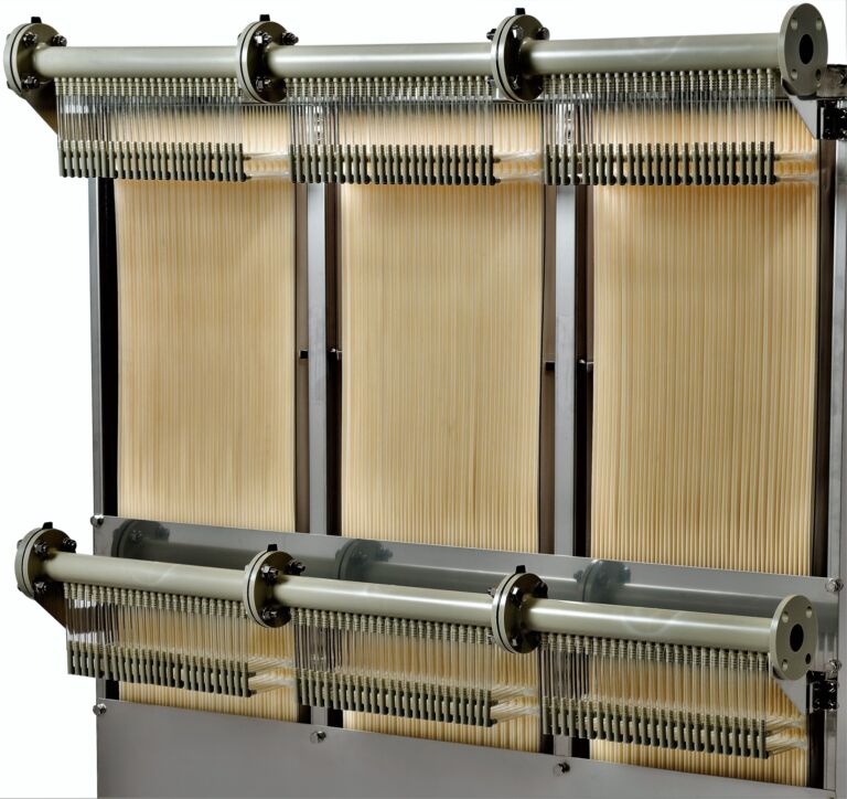
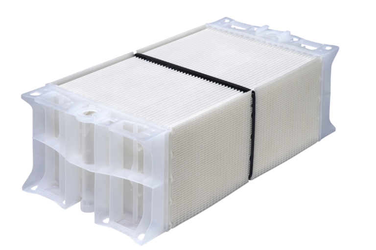
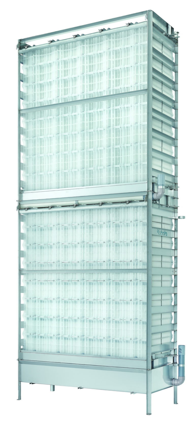
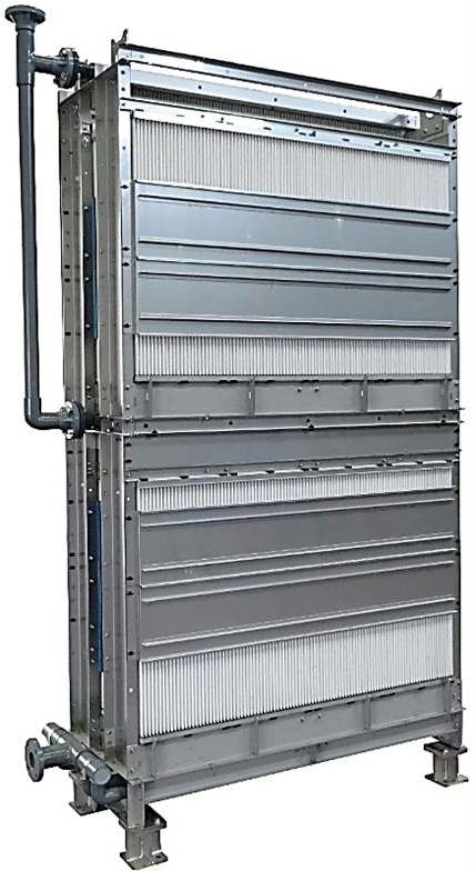
Composite iFS membranes may also be configured as blocks. These have been available for around twelve years, and are designed to be small enough to permit manual assembly of the blocks into a stack. Examples include the Kubota SP-A module (Fig. 5a) and the EnviQ module by QUA. For the Kubota stack (Fig. 5b), the modules are assembled using coupling connections which also serve as a conduit for the permeate.
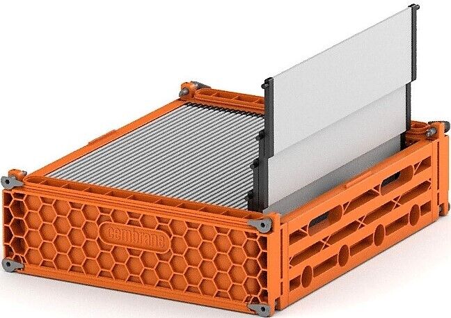
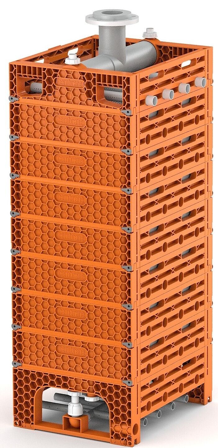
Although considered a recent development, pilot tests on iFS ceramic membranes date back to 2005 and the trials conducted at St Wendel in Germany using the ItN Nanovation membrane. Ceramic iFS membranes are configured either as blocks (Fig. 6), containing a number of short, wide elements, or as long panels (Fig. 7).
2. Membrane materials
The predominant material used for polymeric MBR membranes, and for water and wastewater membrane filtration generally, is polyvinylidene fluoride. Of the sixteen polymeric iFS products considered in this article (Table 1), twelve are PVDF. The other materials used are polyethersulphone (PES), which accounts for three of the products, and chlorinated polyvinyl chloride (c-PVC), used for the Kubota membrane. There also exists a hybrid iFS product, the FibrePlate by Fibracast, where the sheets comprise a series of conjoined horizontally-aligned hollow fibres of 1.3−mm outer diameter, with such sixteen sheets forming a single 37−46 m2 module. This product displays characteristics more akin to a hollow fibre module than a flat sheet.

In the case of the ceramic iFS membranes, the materials used are either alumina, zirconia (usually on an alumina substrate) or silicon carbide (SiC). Examples of two established ceramic products are those from Cembrane in Denmark (Fig. 6), offered in the US by Ovivo and branded SiCBLOX, and Meiden in Japan (Fig. 7). There are other ceramic flat sheet products that are either marketed as MBR technologies (e.g. SafBon-ItN) or offer potential for use in MBRs (e.g. Cerafiltec and LiqTech).
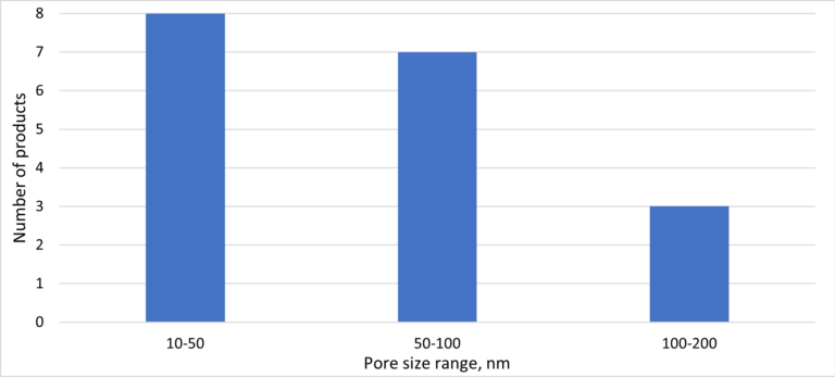
With regards to pore size (dp), all of the eighteen products considered have rated pore sizes between 10 and 200 nm, and predominantly between 10 and 100 nm (Fig. 8). All of the PES membrane products have pore sizes between 35 and 40 nm, and all are the composite type. It therefore seems possible that these products are all based on the same material (for example the MYTEX composite membrane manufactured by WTA Technologies).
A consideration of the module footprint in terms of the membrane area per unit floor area (FA) indicates a roughly linearly relationship between FA and module height. There is considerable scatter for the rigid plate products, based on a plot of FA vs. overall module height and including stacked systems (Fig. 9). However, this is in part due to the different criteria for determining the module dimensions. For those data highlighted in red in Fig. 9, both the footprint of the manifold and the volume between the base of the module and the tank floor (where the coarse-bubble aerator is located) have been excluded. Ignoring these data points indicates an Fv value (the area per unit module volume, or packing density) of 43 m2/m3 ± 24% for the rigid panels, including the ceramic membranes, compared with a corresponding value of 65 m2/m3 ± 21% for the composites.
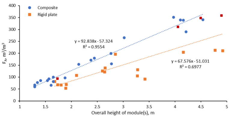
There is a further impact on the footprint associated with the spacing of the modules in the tank. If this is assumed to reduce the FA by a factor of two then, for a 4m−high module, the mean surface overflow rates in m3/d flow per m2 floor area work out as 130 and 86 m/d for the composite and rigid plate membrane modules respectively. This compares to a maximum value of around 30 m/d for a conventional secondary clarifier. There is thus a significant decrease in tankage space occupancy for both membrane module types compared with conventional sedimentation. Moreover, the footprint of an MBR is further reduced compared to the conventional activated sludge process by the higher mixed liquor suspended solids (MLSS) concentrations.
3. Membrane air scour (SADm)
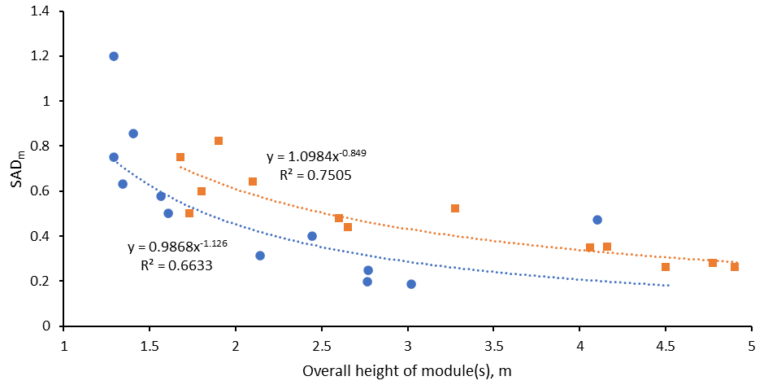
The sludge is air-lifted up through the membrane channels by air bubbles delivered by a coarse-bubble aerator placed beneath the module. The aeration rate is normalised against the membrane area to give the specific aeration demand (SADm) in Nm3/h per m2 membrane area. As is to be expected, the air scour demand decreases with increasing module height, albeit with considerable data scatter (Fig. 10). The decrease in SADm arises because the required aeration rate relates to the module horizontal open cross-sectional area, which does not change with module height, whereas the membrane area increases linearly with module height. The aeration demand appears to be slightly lower for the composite membrane products, though the difference is perhaps not significant compared with the data scatter.
4. Summary
A review of the commercial flat sheet modules used in immersed MBRs reveals there to be:
- two different construction methods (the rigid plate and composite)
- two membrane material types (polymeric and ceramic)
- three different polymeric membrane materials, dominated by polyvinylidene fluoride (PVDF)
- two membrane module shapes (long panels and blocks), and
- rated pore sizes between 10 and 200 nm.
The original immersed flat sheet (iFS) MBRs were based on the rigid flat plate configuration, which is still supplied today. The composite membrane was introduced in the mid-noughties and the ceramic FS membrane shortly after, though has perhaps only started to achieve significant market penetration within the past 5−10 years.
The composite membranes provide a higher intra-module packing density than the rigid plates. The overall packing density is then dependent on the spacing of the modules in the tank. The rigid plate configuration offers the opportunity to replace individual panels.
Whilst it is generally acknowledged that the iFS configuration demands higher air scour rates than immersed hollow fibres, their relative operational simplicity makes it likely that they will continue to be employed in the future.


