MemPulse MBR system vs traditional MBR systems

Victoria Kippax
Victoria Kippax is MBR Product Manager, Asia/Pacific region, for Siemens Ltd, Australia’s Water Technologies Business Unit
1. Introduction
Membrane bioreactor (MBR) systems are becoming more accepted in the wastewater industry as an alternative to traditional conventional treatment systems. A number of factors have been instrumental in the acceptance of the MBR technology.
Firstly, with the growing world water scarcity, the desire to recycle or reuse has increased the application of technologies that provide reuse-quality water. MBR technology provides reuse-quality water with turbidity of typically less than 0.1 NTU and non-detect fecal coliform levels found in ultrafiltration and microfiltration membrane systems. Secondly, an MBR system’s small footprint can be attractive for space-limited applications due to the elevated mixed liquor suspended solids (MLSS) that, in turn, provide higher organic loading and lower sludge production. Finally, the MBR, in replacing the secondary clarifier and tertiary filter, can provide an integrated solution without separate control packages for each unit operation.
2. Importance of Air Scour
For an MBR system, energy requirements are of primary interest. Aeration energy is the largest consumer of energy on an MBR system. This comes in two forms: energy/air − to provide oxygen for biological nutrient removal, and energy − to provide scouring of the membrane to keep it clean. As the air required for biological nutrient removal is calculated in terms of lbs or kg of oxygen, limited optimization can be done.
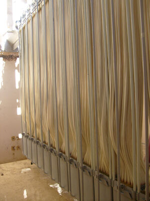
However, MBR suppliers and universities are avidly researching the optimization of membrane air scour energy. The hydrodynamic conditions and system configuration in an MBR system can greatly affect membrane performance. A system’s performance improved by 20−60% when a two-phase (air and liquid) cross-flow was applied rather than just a single-phase (liquid only) cross-flow (Kang et al, 2008).
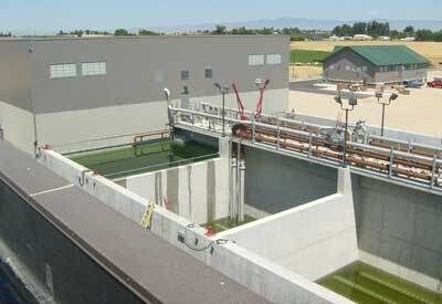
Air scour energy in an MBR system gives high levels of turbulent and surface contact to remove solids particles that attach to the surface of the membrane and to guard against irreversible membrane fouling. Membrane fouling can cause reduced production capacity, shortens membrane life, and increases operational cost. Various technological innovations have been brought to market over the past 10 years to decrease the air scour energy required in an MBR system, where the industry has seen air rates drop by 75% from 1.2 m3 air/m3 filtered to 0.3 m3 air/m3 filtered.
3. Two Aeration Configurations
Different types of aeration configurations affect the use of innovative air scour in MBR systems. Depending on the air and liquid flow rates and the properties of the liquid, the mixture of air−liquid can adopt a wide spectrum of flow patterns. However, in MBR systems where the applied air flow rates are relatively low, the most likely flow regimes are bubbly flow and slug flow (also known as plug flow). Figure 1 depicts two bubble pattern types.
Traditionally, bubbly flow has been applied to the system in various different forms, most commonly through use of a coarse-bubble diffuser. This type of diffuser can be as simple as a pipe with holes drilled into it, individual tubes of the membrane modules, or some form of diffusion grid.
The main drawback with the bubbly flow regime is its relative inefficiency. The small bubbles created in the bubbly flow regime cannot provide enough energy to shear and shake the membrane surface and, as a result, a large amount of energy must be expelled to provide the air scour needed to keep the membranes clean.
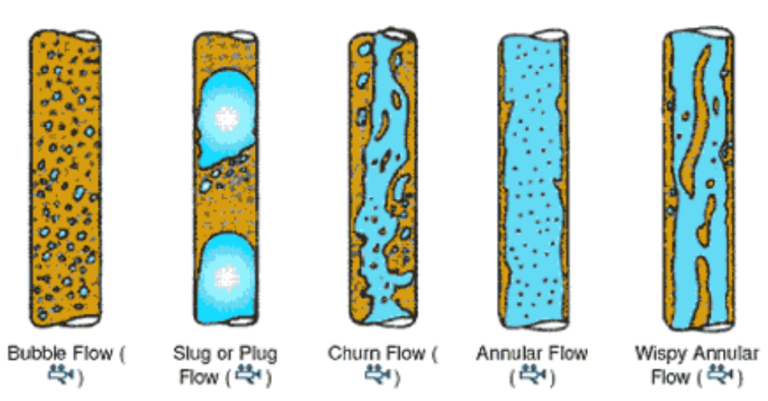
In contrast, the slug or plug flow provides maximum efficiency due to three major factors (Cui et al, 2003). The moving bubbles generate secondary flows behind the initial bubble that assist in breaking up cake layer and subsequently promote local mixing near the membrane surface. A liquid film around the outside of the bubble can be a high shear region, promoting the movement of solids away from the membrane surface. The moving slugs result in pulsing pressure in the liquid around it, causing instability and disturbance near the membrane surface.
The outcome: by utilizing slug or plug flow, the MBR system can provide significantly less air for the same scouring efficiency.
4. Slug/Plug Flow Improvements
One application that now utilizes the slug or plug flow is the MemPulse™ MBR system from Siemens Water Technologies. The system is supplied with a continuous air supply that is accumulated in the base of the module. It periodically releases irregular pulses of air to the MBR module, creating plug flow.
To create the plug flow, the MemPulse MBR system acts as an airlift pump, drawing mixed liquor from below the device through a suction pipe and into the module. The liquid helps to prevent solids accumulation as the mixed liquor on the membrane is continuously refreshed with new liquor.
Table 1. Total power consumption comparisons (supplied by Memcor Products, Siemens Ltd)
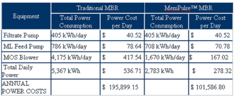
The major difference between the MemPulse MBR system over traditional MBR systems is that the air supply to the system is up to 60% lower. Compared to a similar system with bubbly flow regime, a comparable performance could be achieved with half of the air flow rate.
Equating this to a system design, the energy required for a typical 5 MGD MBR system was reduced by 48% over a traditional MBR system, as shown in Table 1.
In addition to providing a large improvement in aeration energy, the MemPulse MBR system has a secondary advantage over traditional MBR systems. Apart from the accumulation device on the base of the module, no additional equipment is required to produce the necessary air flow.
Traditional MBR systems often provide valves or additional equipment to reduce the amount of bubbly flow supplied to the membrane modules while still maintaining a certain scouring efficiency. This equipment can require increased maintenance and care over the accumulation device, which has no moving parts.
5. Conclusion
The MemPulse MBR system is one more step in the development path of MBR technology. Over the past 30 years, there have been a number of breakthroughs in the MBR field that have seen the total system cost drop dramatically.
These include:
- The introduction of submersed membrane technology rather that tubular modules significantly decreased operating as well as capital costs, due to the lower recirculation rates required and the removal of a separate membrane housing.
- The separation of membrane tanks from the biological system allows for membrane cleaning in place and eliminated the need to remove membranes unnecessarily. It also allows for independent optimization of biological process and membrane performance.
The common theme with all MBR technology breakthroughs is a decrease in operating costs and capital expense, to improve the competitive product of the technology in the wastewater industry. This has allowed the technology to move from a niche small application technology to large municipal applications for 20+ MGD flows. The MemPulse MBR system provides an advantage in the energy required to clean the membranes.


