Kunming Underground MBR: a Chinese case study


Yu Huang
Yu Huang is an alumnus of Cranfield University’s Water and Wastewater Engineering MSc. Since 2008, Yu has worked with Beijing Origin Water Technology Co., Ltd. and Yunnan Water Investment Co., Ltd
1. Introduction
China features many of the largest municipal wastewater MBRs in the world. Apart from their capacity, some also are ambitious in their construction. The installation at Kunming City, commissioned in 2012, is one such example.
At an ADF (average daily flow) capacity of 150,000 m3/d and a peak loading factor of 1.3 (and hence a peak daily flow, or PDF, of 195,000 m3/d), it is a substantial plant. It is also constructed below ground, in compliance with the urban planning of the city, and provides a non-potable reuse water flow of 45,000 m3/d.
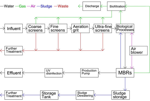
The plant is intended to meet the urban sewage treatment plant pollutant discharge standards (GB18918-2002), Level A standard of 10, 10, 15 and 0.5 mg/L for BOD, SS, TN and TP respectively (Table 1). As well as the use of a membrane bioreactor (MBR) for treating the main flow, the sludge is dewatered by centrifugation and the ventilated air treated by biofiltration.
| Parameter | CODcr | BOD5 | SS | NH3−N | TN | TP |
|---|---|---|---|---|---|---|
Design influent water temperature: Tmin= 12 ℃, Tmax= 28 ℃ | ||||||
| Influent concentration, mg/L | 400 | 180 | 300 | 30 | 45 | 5 |
| Effluent concentration, mg/L | 50 | 10 | 10 | 5 | 15 | 0.5 |
| Removal efficiency, % | 87.5% | 94.4% | 96.7% | 83.3% | 66.7% | 90% |
2. Plant design
2.1 Preliminary treatment
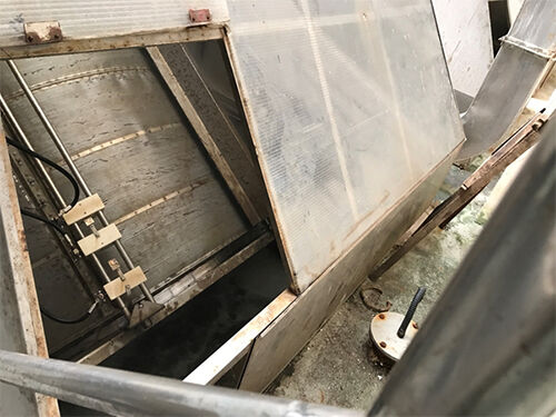
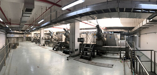
The plant employs three stages of screening. Four 10 mm coarse screens are followed by another four 2 m-diameter 5 mm rotary drum screens followed by grit removal in an aerated grit chamber before final fine screening using six 2.6 m-diameter rotary drum screens rated at 1 mm.
2.2 Tanks, hydraulics and membrane
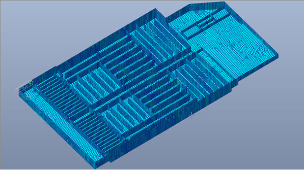
The plant comprises two lines, each including both an anaerobic zone and two anoxic zones for nutrient removal. The two biological tanks each have dimensions of 52.3 wide × 116.3 high × 8.25 m deep, with an effective depth of 7.0 m. The membrane tanks have the same width and are 27.8 m long with a total depth of 5 m, giving an effective depth of 3.6 m. Each membrane line contains 14 trains, 28 in total, with space for ten membrane stacks, nine of which are currently occupied. The total number of membrane units is 252, each containing 46 modules with a design membrane area of 27.5 m2.
At the average flow the total hydraulic retention time is 14.1 h: 1.1 h in the anaerobic zone, 3 h in the anoxic zone, 4 h in the aerobic zone, 4.8 h in the secondary anoxic zone and 1.2 h in the membrane tanks. The design denitrification recycle ratio from the aerobic zone to the first anoxic zone is 3:1, compared to 2:1 from the anoxic to anaerobic zone.
The membrane tanks operate at a recycle ratio of 4−5:1 to limit sludge concentration polarisation in the membrane tank. At these hydraulic retention times and at a solids retention time (SRT) generally above 30 d and loadings of 0.07−0.10 kg BOD5/(kgMLSS.d), the mixed liquor suspended solids (MLSS) varies between 5 and 7 g/L in the process tanks and 6−10 g/L in the membrane tanks.
The DO concentration is kept above 2 mg/L by fine bubble diffusers operating at a design maximum air:water ratio of 5:1, compared with ~0.2 mg/L in the anoxic zones. The biological nutrient removal (BNR) design is based on the introduction of the feedwater at multiple points in the biochemical zones, the ratio between the anaerobic, primary anoxic and secondary anoxic zones being 20:45:35.
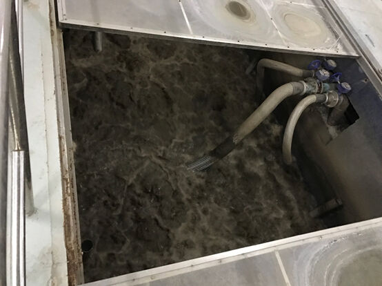
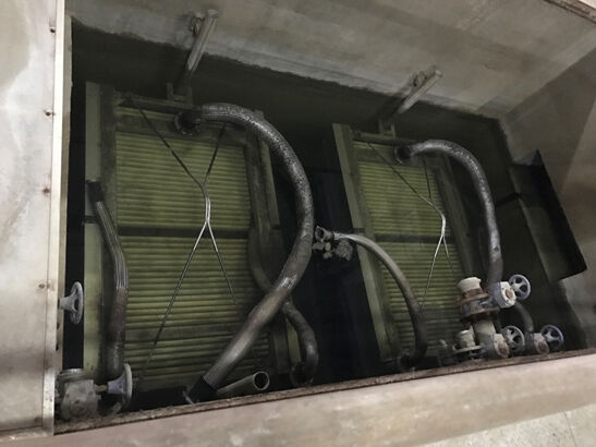
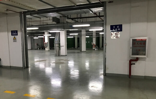
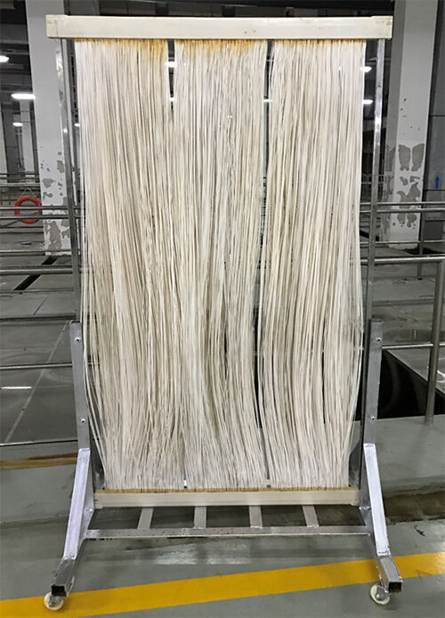
The membrane module is based on a PVDF (polyvinylidene fluoride) hollow fibre (HF) membrane and was supplied by Origin Water of Beijing. It is scoured by coarse-bubble aeration via a perforated pipe at an inlet pressure of 4.5 m water, providing a specific aeration demand (SADp) of 15 Nm3 air per m3 permeate. The average net flux attained is 19.6 L/(m2.h). Permeate is pumped using 30 × 30 kW pumps rated at 334 m3/h flow against a head of 16 m. The 16 kW backwash pumps (duty and standby) are rated at 250 m3/h at a head of 12 m.
12 centrifugal air blowers are installed on the site. The biological process is fed with four blowers with one back-up, all rated at 313 m3/min. The membrane tanks are supplied by six 280 m3/min blowers, with one back-up.
Other pumping operations are for membrane chemical cleaning, achieved with two 18.5 kW centrifugal pumps rated at 535 m3/h against an 8 m head, and sludge pumping using four 1 kW centrifugal pumps rated at 160 m3/h against a 15 m head. The four sludge streams each feed a dewatering process, dosed with polymer, with the extracted dewatered sludge (~20 % dry solids) stored solids fed to two storage tanks by screw pumps.
2.3 Chemicals
2.3.1 Membrane cleaning
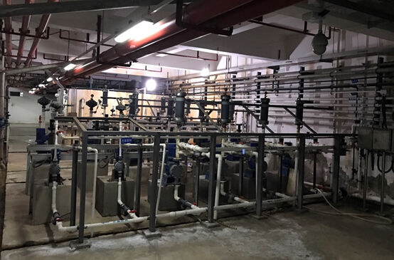
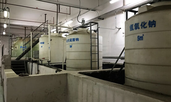
The membranes are cleaned using the classic combination of sodium hypochlorite (NaOCl) and citric acid. The stock solution strength of the two reagents are 10% and 30% respectively. Routine weekly cleaning in place (CIP) is carried out at concentrations of 500 mg/L NaOCl and 0.2 wt% citric acid, the reagents being applied sequentially by back-pulsing through the membrane modules. This is supplemented by similar monthly cleans at higher concentrations of 3000 mg/L and 0.8 wt% respectively, and annual off-line cleaning by immersion in the same reagents at concentrations of 3000 mg/L and 2 wt% respectively. The offline clean employs reagent flows of 6000 L/h and take a day, compared with 2273 L/h for the monthly cleans and around 765 L/h for the 40-minute weekly cleans.
The spent NaOCl and citric acid cleaning reagents are respectively dosed with 30% sodium thiosulfate and 45% sodium hydroxide prior to discharge. The annual consumption of these two chemicals is 2.06 and 3.29 tonnes respectively.
2.3.2 Final water disinfection
The non-potable water reuse disinfection system is dosed via a diaphragm metering pump at a rate of 141 L/h with a 10 wt% NaOCl solution, stored in three 12 m3 tanks, to a concentration of 6 mg/L as Cl2. The 1.5 kW pump is rated at 300 L/h against a pressure of 3.5 bar.
2.3.3 Nutrient removal and balancing
Chemical removal of the residual phosphorus from the BPR process is through polyaluminium chloride (PACl) dosing at 12 mg/L from a 10% stock solution at a rate of 490 L/h. The stock solution is prepared daily in a two-compartment 18 m3 tank.
Carbon balancing is conducted using 40%−50% sodium acetate, dosed according to the C/N ratio at a rate of 30−90 mg/L BOD equivalent.
2.4 Ventilation
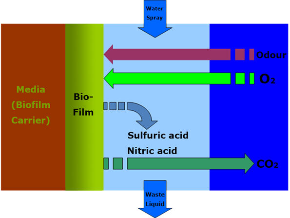
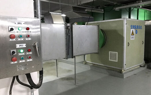
The air is treated by biofiltration based on a trickling filter with a specialised media which is fed with a nutrient solution (N, P and trace elements) to sustain the biofilm. Volatile organic carbon (VOC) and sulphurous and nitrogenous species are either assimilated in the biofilm or converted to sulphate, nitrate and CO2. The wastewater from this operation is fed to the aerobic tank and the treated, deodorised gas vented to the atmosphere.
3. Plant performance
A daily log is taken of all main sludge quality parameters, including filterability, sludge volume index (SVI), MLSS, MLVSS and so the F/M ratio at the operating SRT. The comparatively low organic loadings have led to extremely low F:M ratios (~0.01 d-1) along with the tendency to accumulate inert material in the tanks, the latter indicated by MLVSS/MLSS ratios below 0.5.
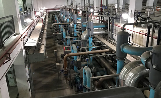
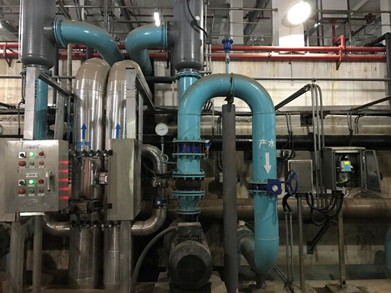
The low organic loads arise for a number of reasons. Firstly, there is infiltration by river water due to the condition of the collection system. There is also dilution from storm water. Lastly the Chinese diet − very low in dairy products − tends to produce lower concentrations BOD and COD.
Despite these challenges the plant has operated without any major issues at an average overall specific aeration demand of 0.5 kWh/m-3. It is just one example of the large number (at least 15) of >100 MLD capacity MBR plants operating in China based on the Origin Water membrane technology, and is an indication of the country’s ambition in implementation of the technology.


