Improving MBR flux: Ultrafiltration with a twist

Radek Oborný, Patrick van Lierop and Roy Rosink
Pentair’s Radek Oborný, Patrick van Lierop and Roy Rosink report on three case studies employing Helix, Pentair’s flux-enhancing technology − Ootmarsum, Hooge Maey and an anaerobic MBR pilot at a brewery
1. Introduction
As a maturing technology, membrane bioreactor design has evolved into three distinct camps over the last few decades − submerged flat sheet membranes, submerged hollow fibre membranes, and finally externally-placed tubular membrane modules operated in crossflow or Airlift (such as those offered by Pentair). Much has been written about the pros and cons of these different approaches, but it can be said of all of them that each is now an established technology configuration in its own right.
Despite the maturity of the technology, work continues to optimise the performance of membrane bioreactors. Current areas of focus include reducing energy consumption, increasing flux and improving the stability of operation, all of which are essential to improving plant efficiency and productivity.
In autumn 2015, after two years of research and development, Pentair brought to market its new ‘Helix’ product. An enhancement to X-Flow tubular membrane technology, Helix features a helically-winding ridge on the inside of the membrane which is designed to tackle cake build-up and enhance flux. The technology has so far been tested on both industrial effluents and municipal wastewater, and at both pilot-scale and full-scale plants, as well as in crossflow anaerobic, aerobic and Airlift MBRs. Testing has been carried out at Ootmarsum (Netherlands), an anaerobic MBR pilot located at a brewery, and a crossflow MBR for leachate treatment in Hooge Maey in Antwerp. The research suggests that the Helix has increased membrane flux by up to 100%, with the effect of markedly improving installation productivity, lowering specific energy consumption and encouraging more stable filtration performance.
2. About external circulation MBRs
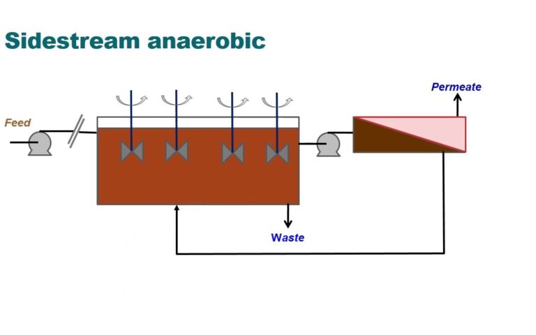
In an external circulation MBR, the sludge produced in the reactor is pumped into externally-placed modules, the overpressure created on the inside of the tubular membrane (transmembrane pressure, TMP) serving as a driving force for permeation. The inevitable consequence of filtration is the build-up of cake which lowers fluxes. In tubular membranes, the cake build-up and concentration polarisation are being held at bay by means of crossflow velocity (CFV), periodic back-washing with permeate and − in the Airlift design − by Taylor bubbles.
The main advantages of placing the membranes externally are the ability to accurately control process conditions, TMP and CFV, to carry out flow reversal for removal of coarse material and fibres and, when membranes foul, to clean-in-place (CIP) the isolated skid. Additionally, operators can access modules for maintenance without being exposed to sludge.
The tubular membranes provided by X-Flow are available in 5.2 mm- and 8 mm-internal diameter, conventionally in a 3-metre-long module, the choice of the membrane being dependent on the particular type of skid design. Traditional high-speed crossflow membranes (2–4 m.s-1) use the large-diameter membrane modules in series with a focus on high fluxes, minimising the pressure drop and preventing blockage. Airlift and low-speed AnMBRs use the smaller-diameter membranes and operate in parallel flow with a crossflow velocity of less than 1 m.s-1. The low crossflow is preferred when low energy consumption is the main goal such as in the municipal market and anaerobic technology.
In continuous ultrafiltration, the flux is proportional to the shear stress [τw] applied to the membrane wall. Assuming the sludge behaves as a Newtonian liquid and is subject to laminar (Re <2500) Newtonian flow, the shear stress τw is proportional to the pressure difference [ΔP] over the length of the membrane [lm] and the tubular membrane diameter [Dm]:
In order to sustainably double the flux, the shear stress at the wall needs to increase by a factor of two. This is conventionally achieved by doubling the crossflow rate Qm (i.e. the crossflow velocity). Such an approach, however, leads to increasing the pumping energy [Ep] by a factor of roughly four, since both [ΔP] and [Qm] are doubled:
This is not economical and has often limited the applicability of tubular membrane-based MBRs to small-scale industrial streams where energy consumption is not a determining factor. To tackle this issue and provide a high flux at low crossflow, Pentair has developed the ‘Helix flux-enhancing technology’.
3. About the Helix flux-enhancing technology
The Helix technology has been developed to harness the energy contained in the crossflow and, at low crossflow velocity, enhance the shear stress to boost the flux.
Helix membranes (Fig. 1) feature a helically-winding ridge on the inside of the membrane. The ridge is made from the same material as the surrounding membrane, takes part in the filtration and is backwashable. There are no sharp edges or pits where rejected material can accumulate and cause blockage, as opposed to the net-like spacers used in spiral-wound modules which promote turbulence but do so by partially filling the channel [1].
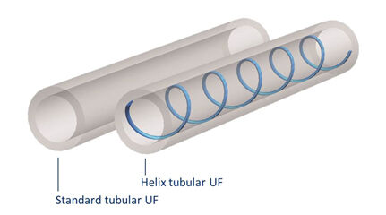
Two mechanisms are at work in the Helix membranes:
- The induction of secondary flows − Dean vortices − at the ridge structure (Fig. 2a) [2]
- Forced helical flow of the feed stream along the membrane and increased wall crossflow velocity (Fig. 2b).
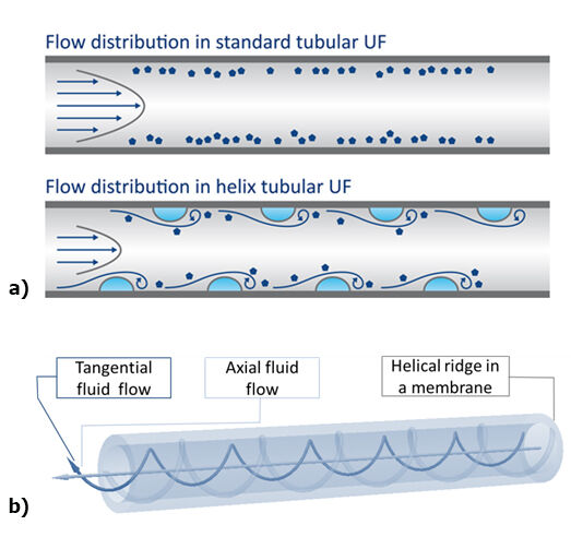
Both of these mechanisms, which possibly work synergistically, have the effect of increasing the shear stress at the membrane wall and so promoting the flux at a low crossflow velocity.
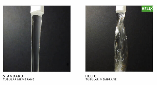
A visual demonstration of the Helix function is provided in Figure 3. Two pieces of 8-mm membrane, 300-mm in length, have been challenged with the same flow rate of 300 l·h-1 of clean water, equivalent to a 1.65 m.s-1 CFV. The outflow from the Helix membrane is clearly more turbulent and shows a helical twist in comparison to the standard.
To show their applicability in real streams, the Helix membranes have been employed at both pilot-scale and full-scale, and under aerobic and anaerobic conditions, at Ootmarsum and Hooge Maey (aerobic operation) and at a brewery (anaerobic operation), all with encouraging results.
4. Case study 1: Ootmarsum, Netherlands − municipal Airlift MBR
4.1 The principle of Airlift filtration
The Airlift concept of filtration has been designed with a focus on minimising the energy consumption in large-scale applications such as municipal wastewater filtration. In these applications, large volumes of low-COD water have to be processed to ensure nutrient removal.
The Airlift concept introduces gas flow into the membranes, together with crossflow, thus creating a multiphase flow. The type of bubble created depends on the amount of injected air [3] as shown in Figure 4.
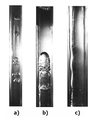
When aeration is insufficient, the bubbles formed are too small (Fig. 4a) and don’t produce the desired effect. On the other hand, when a large amount of air is supplied, annular flow ensues, leading to excessive air use (Fig. 4c). When the volume of air flow is correctly selected, slug flow – also known as a Taylor bubble – forms (Fig. 4b). As the bubble rises through the membrane, a turbulent wake is created which disrupts cake formation and leads to an increase in flux. Since the bubble is in contact with the membrane along its whole length, cake removal takes place over the whole membrane surface.
The secondary effect of Airlift is the aeration of the sludge which leads to a reduced aeration requirement in the bioreactor.
When the Taylor bubble ascends through a tube with helicoidal corrugation, as with the new Helix design, it could be expected that additional vortex shedding takes place, further enhancing the effect. Indeed, flux enhancement was observed in research conducted at Ootmarsum, Netherlands, an MBR based on the Pentair AirLift filtration process.
4.2 Pilot- and full-scale studies at Ootmarsum
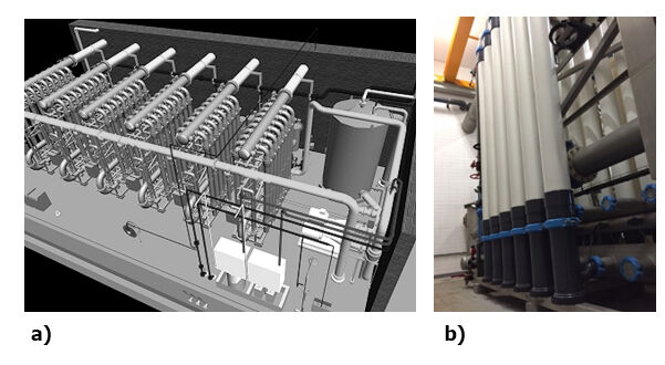
A full-scale study at WWTP Ootmarsum started in February 2015 and, at the time of writing, is still running. The installation consists of six skids as shown in Figure 5a. Twelve 8” modules of the 33V type, equating to 396 m2 of membrane area, fitted with Helix membranes replaced the standard modules, operational since 2007 (Figure 5b). The results were directly compared to another skid equipped with standard 5.2 mm tubular membranes. To ensure a fair test, the opportunity was taken to examine the removed modules. After standard chemical cleaning with sodium hypochlorite, the membranes showed comparable strength, clean water permeability and filtration performance as unused membranes.
In this on-going full-scale study, the filtration cycle comprises:
- crossflow filtration with aeration, sludge velocity 0.45 m.s-1, air velocity 0.22 m.s-1 lasting 14.5 minutes
- backwash for 10 seconds at 250 l.m-2.h-1
- module drainage every 16 filtration–backwash cycles.
To determine the critical flux, filtration flux has been stepped up and the TMP evolution during the filtration cycle observed [4]. The maximum operational flux is defined as the maximum attainable flux with a stable TMP evolution. In practical terms, the TMP needs to increase linearly during the 15-minute filtration at a constant flux, with a maximum end TMP of 0.28 bar. The operational data comparing two skids are shown in Figure 6.
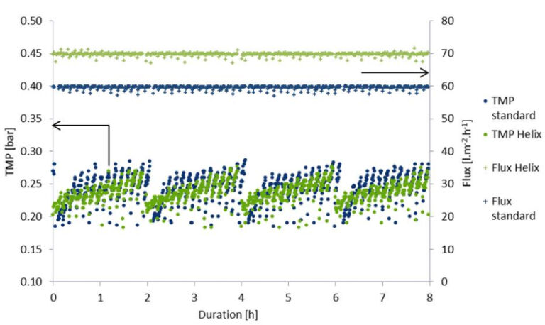
Several months of stable operation showed that the Helix membranes had a significantly higher flux than the standard under the same operating conditions. The test resulted in a net capacity increase (filtrate minus backwash volume) of 20% for the Helix membranes and more stable TMP development. Furthermore, the specific energy demand for the AirLift process was reduced by 20%. The results are summarised in Table 1.
| Parameter | Standard 5.2 mm tubular membranes | Helix 5.2 mm tubular membranes |
|---|---|---|
*Energy consumption required for bioreactor or equipment outside the UF process not included in energy balance | ||
| Operational flux | 60 l.m2.h−1 | 70 l.m2.h−1 |
| Net flux | 51 ± 1 l.m2.h−1 | 60 ± 1 l.m2.h−1 |
| Specific energy demand* | 0.25 ± 0.05 kWh/m3 | 0.21 ± 0.05 kWh/m3 |
Future research at the full-scale AirLift MBR at Ootmarsum will show if further improvements are possible by optimising the AirLift process conditions specifically for the new Helix membranes.
Note: The Ootmarsum AirLift MBR installation may be visited by the public, so please contact Pentair if you are interested in seeing this process in action.
5. Case study 2: Anaerobic AnMBR pilot − brewery wastewater
The X-Flow Helix membranes have been tested at an anaerobic MBR pilot located at a brewery. Brewery wastewater is considered as a medium-to-low COD (Chemical Oxygen Demand) wastewater. Traditional UASB and EGSB reactors can be operated at high loading rates and low HRTs, and relatively large flows of wastewater are treated in these systems. Due to the fine solids found in anaerobic MBR sludge, a dense cake layer builds up rapidly [5], which leads to low fluxes compared to aerobic MBRs, and thus a requirement for large installed membrane area. To compete with the current highly efficient conventional anaerobic treatment systems, the CAPEX and OPEX of an AnMBR process need to be reduced.
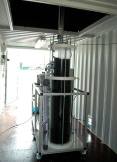
The pilot, shown in Figure 7, consists of a 100 l anaerobic reactor and two vertically placed modules. The anaerobic reactor was operated at a volumetric loading rate of 4−6 kgCOD·m-3·day-1 and at a temperature of 37 °C. The sludge TSS is in the range 15−20 g/l. The pilot was fed with wastewater from a pre-acidification tank. The COD removal was on average 98−99%.
The skid consists of two modules, each three metres long, fitted with six 5.2 mm tubular membranes. Modules are placed in series in crossflow, with independent peristaltic permeate pumps and flow meters to control the permeate flux accurately. Pressure drops ΔP and TMP were measured by meters on the feed, concentrate and permeate side of each module.
The filtration cycle involves:
- 15-minute filtration
- 5-second backwash
- crossflow direction reversal after 16 filtration–backwash cycles.
The pilot automatically searches for the maximum sustainable flux [4] by monitoring the TMP at the start and end of the filtration. Conventionally, tubular modules operate at a flux of 14−17 l.m-2.h-1. With the Helix membranes installed, the flux has risen to 30−35 l.m-2.h-1. The clear difference is observable in Figure 8.
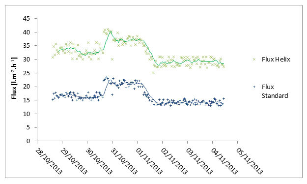
In the presence of the helical ridges, the ΔP has risen from 0.1 bar to 0.15 bar over the 3-m membranes. However, since the flux has doubled and the pressure drop has only increased by 50%, the specific energy consumption is lowered by 25% with the Helix membranes. Such a drop in OPEX makes anaerobic MBRs more economically attractive. More importantly, in this particular case, only half of the membrane area in Helix has to be installed to treat the same volume of feed, significantly reducing the CAPEX of the full-scale system.
6. Case study 3: Hooge Maey, Belgium − full-scale crossflow MBR
The first full-scale installation equipped with 8-mm Helix membranes was a crossflow MBR for leachate treatment in Hooge Maey in Antwerp Port. The plant consists of two identical skids which operate at fixed crossflow velocity of 3.5 m.s-1. One skid consists of six 8” membrane modules connected in series (Fig. 9). The client was willing to replace one skid with the new Helix membranes (green GRP modules) and operate alternately with standard membranes (in the background).
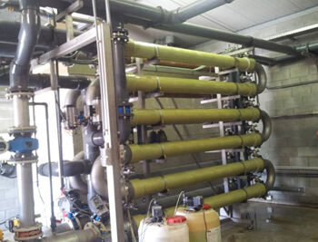
The modules were installed in May 2015. Since the installation, the client has been operating alternately between the two skids. From the first minute of operation, the productivity of the Helix skid was 80% higher than of the standard skid (Fig. 10).
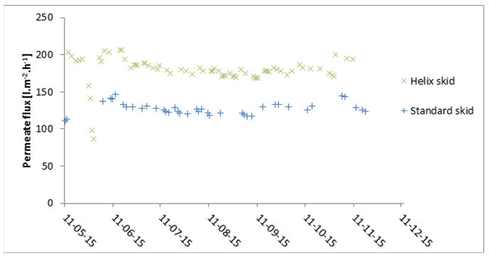
At the start of the test on 12−13 May the standard skid operated at flux 112 l.m-2.h-1 whereas the Helix operated in excess of 200 l.m-2.h-1. By the end of May, the membranes fouled rapidly due to a change in the MBR biology resulting from a contamination in the influent. After a thorough CIP of both skids, the fluxes returned, with the Helix performing on average 40% better than the standard. The client is very satisfied with the results as a result of flux enhancement − the newly fitted membranes have both reduced the energy bill and provided spare filtration capacity.
Importantly, the permeate quality from both skids is equal as the Helix membranes are chemically identical to the standard membranes, both being a hydrophilic–PVDF blend.
6. Summary
In each of the three different types of installations presented here, the Helix tubular membranes have resulted in increased operational flux. This came at a cost of increased pressure drop but, in every case, the specific energy requirement (kWh/m3 permeate) has decreased. Table 2 offers a complete summary of the tested projects, including technical details.
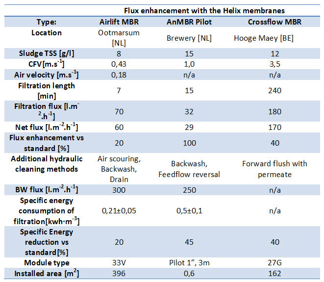
The increased flux is of great importance for potential clients since the installed membrane area requirement reduces significantly. Likewise, current installations retrofitted with the Helix membranes can operate at a higher capacity or lower crossflow velocity and energy consumption. It is, however, important to add, that the ‘flux enhancement’ is application-dependent and piloting is recommended to determine its extent.
Since 2013, a number of different MBRs and wastewater streams have been tested. In the future, it is intended to develop the membrane structure further and build understanding about the working of the Helix membranes by varying the process conditions and testing diverse streams. For that, co-operation with partners is vital − new partners interested in testing the Helix are invited to contact us.
In the six months since its official launch at WEFTEC, the Helix technology was recognised as the ‘Water innovator of the Year 2016’ on the Dutch platform Watervisie [6].


