Mechanical shear in membrane bioreactors


Tamas Zsirai and Simon Judd
Tamas Zsirai (right) and Simon Judd of the Gas Processing Center, Qatar University talk shear, flux and energy demand.
1. Shear in membrane processes
In membrane separation systems, it is probably shear which is the most significant parameter for driving the membrane process. OK, pressure is obviously important for forcing the water through the membrane − though not for extractive systems like electrodialysis and forward osmosis − but shear is arguably the property of the system which largely determines the rate of membrane fouling and so, ultimately, the flux.
Over the normal range of operating conditions, the greater the shear, or specifically the shear rate γ, the greater the flux J. The general relationship is:
where k and n are constants.
So, what is shear? Delving into the nearest on-line dictionary (oxforddictionaries.com) reveals the definition: ‘a strain produced when layers of a fluid are laterally shifted in relation to each other or a surface’. So, when a fluid flows parallel to a stationary surface, the property defining the flow profile is the shear rate γ (the rate at which shear is applied) in units of inverse seconds (s-1). γ actually equates to the rate of change of velocity u with distance x from the surface (i.e. du/dx). If a force is applied parallel to the surface then the ratio of the force to the area over which it acts is defined as the shear stress τ. γ and τ are then related by the fluid viscosity μ:
This relationship was first surmised by Newton, who knew a thing or two, and only actually applies to so-called ‘Newtonian’ fluids (like water). MBR sludge isn’t Newtonian in behaviour, but the general relationship still applies: to generate more shear (and so a higher flux, according to Equation 1) demands a greater rate of change in velocity relative to the surface, the surface being the membrane.
This basically implies that shear increases with increasing fluid crossflow velocity. This is why pumped sidestream MBR (sMBR) systems can generate a higher flux than immersed systems (iMBRs): the shear is greater because the sludge is pumped through the multitube membrane elements at a rate of 2−4 m/s. Immersed systems rely on air bubbles to generate shear as they pass up through the immersed membrane module comprising vertical flat sheets or hollow fibre bundles. And they do this pretty well, but can’t generate the same sort of shear as for the pumped sMBR membranes.
2. Energy demand
As with all things in life, you don’t get anything for nothing. Pumping liquid uses energy, and the faster the liquid is pumped, the more energy is consumed (or power required). A stage is reached where the power needed to pump the water (or sludge, in the case of an MBR) doesn’t produce the commensurate increase in flux. This is simply a reflection of the fact that n in Equation 1 is normally less than one (other than at extremely high shear rates). So, even though it’s possible to pump the sludge through the membrane channels faster than 4−5 m/s − the maximum value normally employed in sMBRs − it isn’t usually worth it in terms of the volume of permeate produced per unit energy expended.
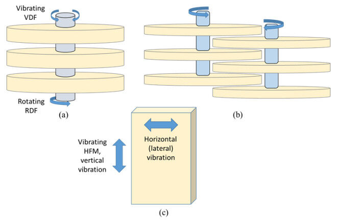
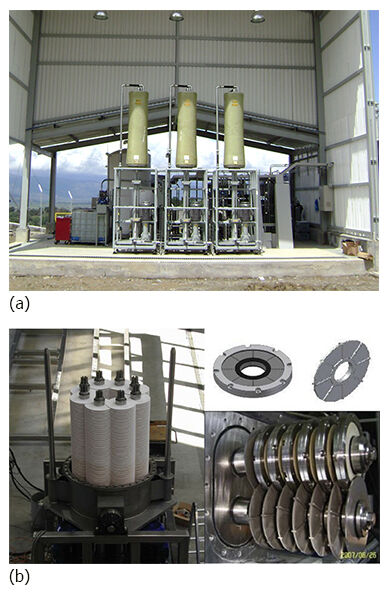
But, pumping the liquid isn’t the only way of generating shear. The alternative is to move the membrane, either by spinning it or vibrating it − so-called ‘mechanical’ shear. There are a few commercial membrane technologies which apply this principle, all using disc membranes − so either rotating or vibrating disc filtration (RDF or VDF respectively, Fig. 1a). Commercial technologies have in the past been configured as multi-shaft disc (MSD) technologies configured with overlapping discs (Fig. 1b and Fig 2b). The most established mechanical shear membrane technology is New Logic’s V-Sep process (Fig. 1a and 2a), a stacked-disc membrane module which can be vibrated at ~50 Hz.
3. Moving membranes and MBRs
As far as MBRs are concerned, Huber’s VRM (vacuum rotating membrane) technology has been around for at least a dozen years, but in this case the membrane is rotated very slowly (1−2 RPM). Such speeds aren’t intended to generate shear but to allow more efficient air scouring. On the other hand, the more recent BioBooster, from Grundfos, rotates the disc membranes at speeds of 100 RPM or more.
The BioBooster is a true RDF system, generating high shear through rotating the membrane and promoting the flux accordingly. There have also been experimental studies of vibrating hollow fibre membranes (VHFMs), with both vertical and lateral displacement of the membrane (Fig. 1c) studied for MBR applications. However, there are no commercial examples of VHFMs, and apparently very few studies even at bench scale of vibrating immersed flat sheet (FS) membranes.
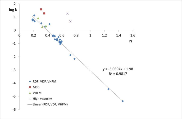
So, how much flux can be generated from increasing the shear rate? Interestingly, for reasons which are currently unclear, the k and n values in Equation 1 seem to be related − at least for membrane systems using mechanical shear (Fig. 3). Across a wide range of studies of rotating or vibrating disc membranes, including VHFMs (the triangular data points in Figure 3), the general correlation between the flux in L m-2 h-1 and the shear rate in s-1 appears to be represented by (Zsirai et al, 2016):
There are some exceptions to this correlation. Very high viscosity fluids and multiple shaft disc (MSD) membrane technologies, respectively the purple crosses and red squares in Figure 3, appear to give much higher fluxes than Equation 3 suggests. Apart from these anomalies, the flux attained seems to follow Equation 3 regardless of the technology − whether RDF, VDF or VHFM.
All of which leads to the next question: Which is best – pumped or mechanical sMBRs? At the moment, it isn’t known whether Equation 3 holds for conventional pumped crossflow systems, though it seems quite likely that it does. The key advantage of a mechanical shear system, however, is that the shear attainable is only limited by the speed of vibration or rotation − which can be very large indeed. Figure 3 includes data relating to shear rates of up to 300,000 s-1, far higher than those attainable from a classical pumped crossflow sMBR. However, as already pointed out, obtaining such high shears, and the accompanying high fluxes, demands power, with the power increasing approximately linearly with rotation speed. High shears are also known to break up flocs, leading to the release of extracellular polymeric substances (EPS) which can then foul the membranes. On the other hand, fluxes in excess of 150 LMH have been recorded at some full-scale crossflow sMBR installations treating food effluents, despite the floc breakage induced under the high-shear conditions. This suggests that floc breakage isn’t a show-stopper in sMBR systems.
Ultimately, as with any water or wastewater treatment process, a key metric is always the specific energy demand (SED) in kWh energy consumed per m3 of water treated (or, alternatively, the power in kW per m3/h of flow). Interestingly, both the pumped and rotating membrane technologies are capable of operating at an SED of around 0.4−0.6 kWh/m3 for a typical food-processing wastewater, with the net fluxes also being roughly comparable. Both technologies can also operate flexibly with regards to the generation of shear. The classical pumped crossflow technologies can be fitted with variable speed drive (VSD) pumps to allow the crossflow to be increased if higher fluxes are required (i.e. at peak flows). For the RDF system the flux can be increased by rotating the membrane more rapidly. In both cases this leads to a lowering of energy efficiency, such that the SED is increased. Crucially though, the technologies both offer the option of permitting higher flows when required through a straightforward adjustment of the operating condition − simply turning a dial.
4. Now what?
Which leads to the final question: If controlling shear mechanically is possible for a sidestream MBR, why can’t the same thing be done for an immersed technology? The few studies of VHFMs suggest that there may be an energy benefit, but air scour remains the most convenient method for maintaining shear in immersed systems. There is some evidence to suggest that increasing the membrane air-scour rate can permit higher fluxes, at least for the FS configuration, but there is less evidence of the same trend applying to HF membranes. So, for immersed membranes, and for HF ones in particular, the option of increasing the shear to allow for periodically higher fluxes may not be viable − which is why a conservative design based on peak fluxes is always required for iMBRs. Designing a membrane module so as to allow mechanical shear to be applied to immersed membranes is not without its challenges. It remains to be seen whether these challenges will ever be considered worthy of addressing.


